Learn how a 3D scan is converted into editable CAD using mesh cleanup, alignment, feature extraction, reverse engineering, and scan-to-CAD verification.
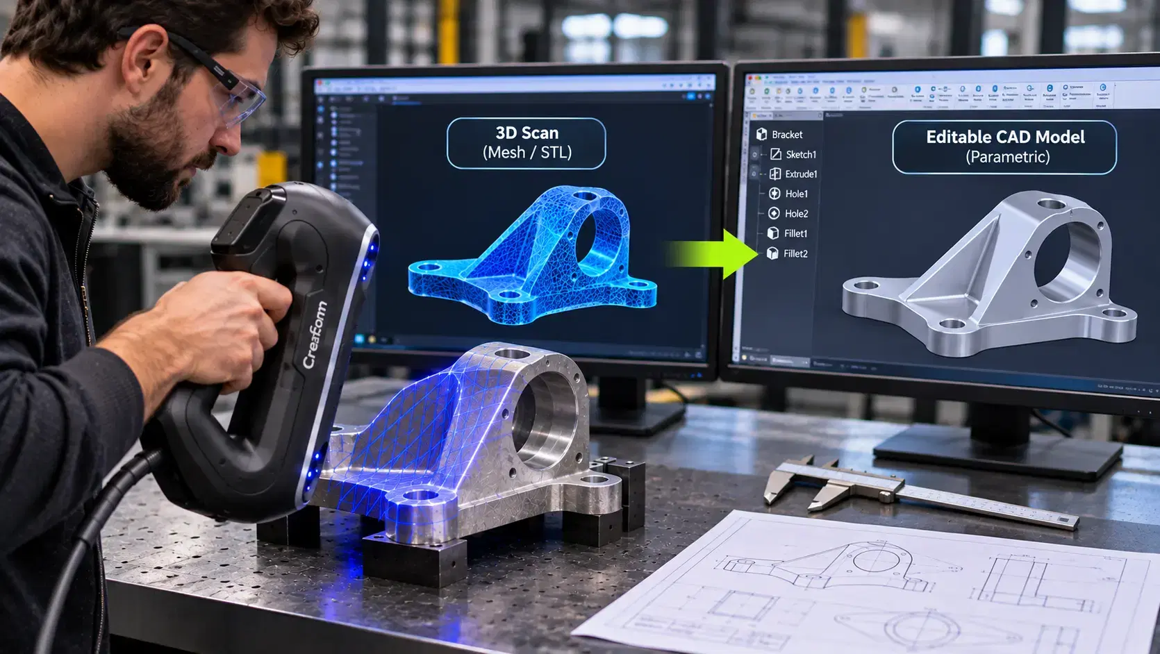
A maintenance team has a worn pump bracket but no drawing. A technician captures its shape with a handheld scanner and sends the resulting file to engineering. The designer opens it, sees thousands of triangles, and asks a question: Where are the editable holes, planes, and dimensions?
A 3D scan can become an editable CAD model, but conversion usually requires reverse engineering. Scanning records the surface; modeling reconstructs the features an engineer can change.
A scanner measures visible surfaces and creates a point cloud or polygon mesh. The mesh consists of many connected triangles that describe the object's shape. It is excellent for visualization, comparison, and certain manufacturing workflows.
Parametric CAD works differently. Engineers build sketches, extrusions, holes, fillets, and surfaces with dimensions and relationships. Changing a hole diameter in that model may update dependent features.
Simply opening an STL file in CAD does not create that design history. Even converting triangles into a solid body may leave a difficult-to-edit collection of faces rather than features.
Start by defining the intended output. A replacement machined component needs different information from a decorative replica or an inspection reference.
Clean the part and check whether damage, corrosion, or wear should appear in the final model. A worn bore measures the current condition, not necessarily the original design diameter.
For 3D scanning handheld applications, secure the object and plan access to critical surfaces. Position any required tracking targets according to the scanner's instructions. Capture multiple overlapping views, including edges, pockets, and mating faces.
A 3D scan laser system projects light onto the surface and uses optical measurements to establish geometry. It cannot recover hidden walls or internal passages without suitable access. Use probes, drawings, or additional measurements when necessary.
Before leaving the setup, inspect coverage. Reaching an inaccessible face later may require repositioning the part and establishing another alignment.
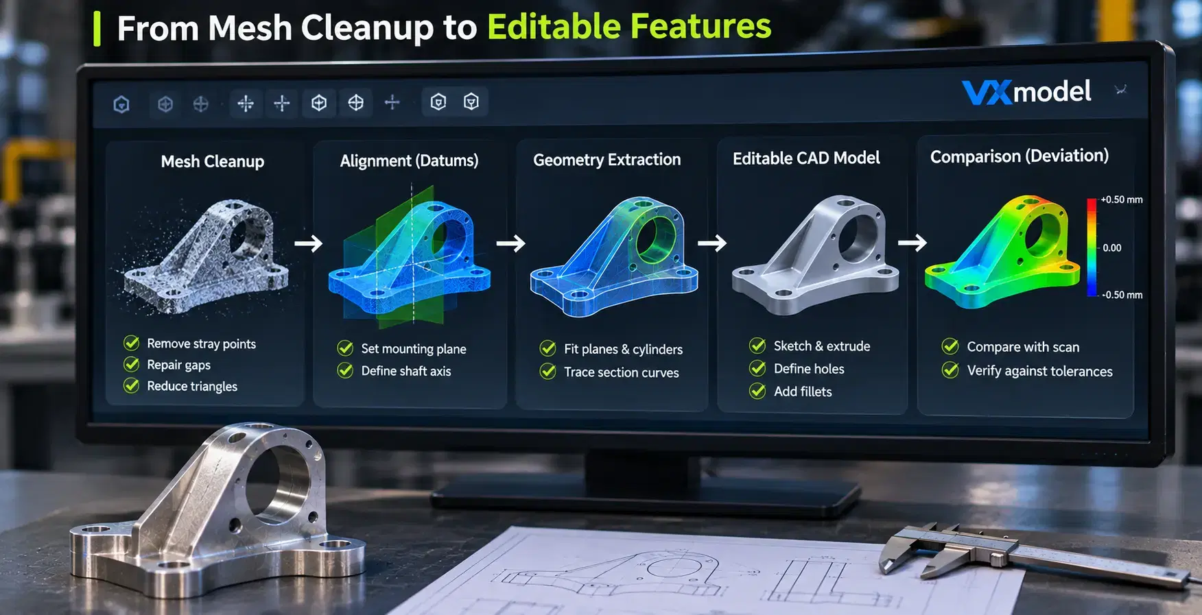
The first processing stage removes stray points and unwanted scan artifacts. Technicians may merge passes, repair gaps, and reduce excessive triangles. Keep an untouched copy so cleanup never erases evidence of genuine defects.
Next, align the mesh to meaningful datums. A mounting plane and shaft axis often provide a better engineering reference than automatically minimizing differences across the whole shape.
Then extract geometry. Software can fit planes and cylinders, trace section curves, and derive surfaces from measured data. These references guide new sketches and features inside CAD.
For example, rebuilding a bracket might involve sketching its outline, extruding the main body, defining mounting holes, and adding fillets. The designer controls dimensions instead of accepting every irregularity captured on the worn part.
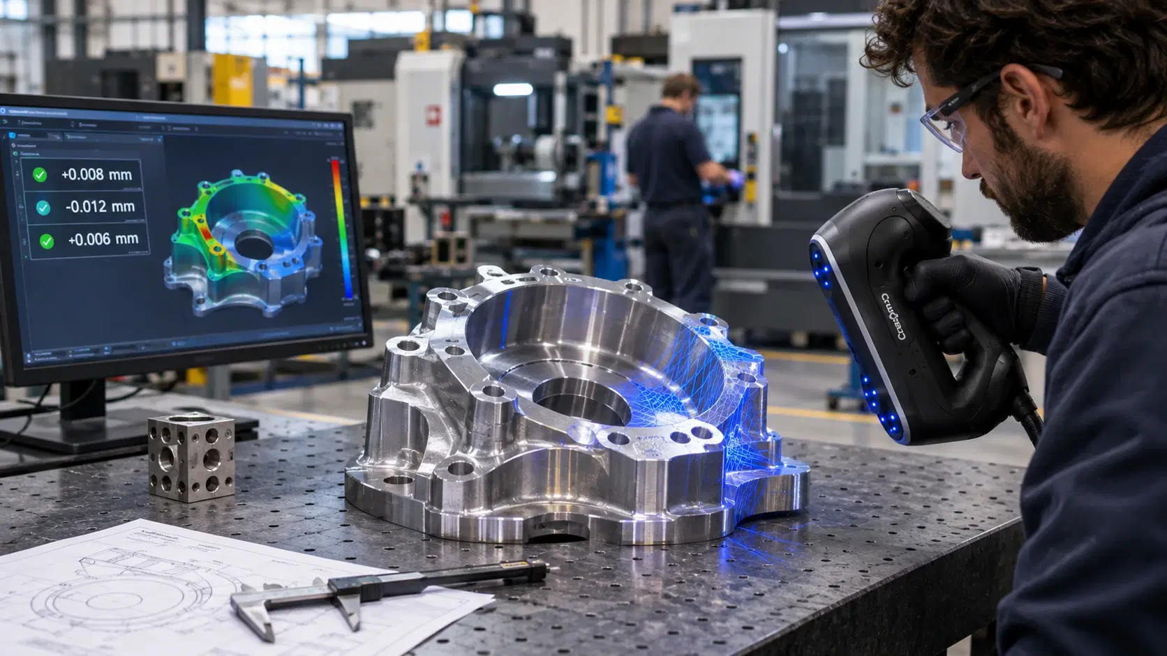
Finally, compare the reconstructed CAD model against the original scan. A deviation map highlights regions where the model differs, but acceptance depends on the drawing, intended function, and tolerances.
Creaform's handheld scanning systems capture surface geometry, while its Scan-to-CAD software prepares data for engineering workflows. The software supports mesh editing, alignment, geometric entity extraction, and transfer to compatible CAD applications.
The offering includes Scan-to-CAD and Scan-to-CAD Pro, with different modeling capabilities. Supported transfer workflows include SOLIDWORKS, Autodesk Inventor, Fusion 360, and Solid Edge; available functions depend on the licensed edition.
A direct transfer can save manual steps, but it does not remove the need to verify datums, hole sizes, fits, and design intent. A polished mesh is not proof of a manufacturing-ready model.
Freeform castings, sculpted surfaces, and organic shapes may require fitted NURBS surfaces rather than straightforward extrusions. Reconstructing them can demand more judgment and time than modeling a simple machined plate.
Reflective finishes, inaccessible pockets, flexible parts, and damaged edges also affect scan quality. More data does not solve every uncertainty. Confirm whether the required accuracy fits the feature's tolerance before promising an exact digital replacement.
Finally, distinguish documenting a part as found from redesigning it as intended. A replacement part must fit its assembly, not merely resemble a distorted original.
Yes, through reconstruction or suitable modeling tools. Basic conversion to a solid does not automatically create editable sketches, dimensions, and feature history.
Some software workflows export STEP geometry, but the file format alone does not guarantee a fully parametric model. Check what the exported file actually contains.
Accuracy depends on scanner performance, setup, feature accessibility, reconstruction choices, and verification. Evaluate critical dimensions against the required tolerances rather than assuming the mesh is exact.
It often captures complex external geometry efficiently. Simple parts or hidden precision features may still be faster to measure with calipers, gauges, or a coordinate measuring machine.
Bring a component, its mating requirements, and any drawings to a demonstration. Ask to see not just the scan, but an editable feature, a dimensional check, and a usable CAD deliverable.
Dynamic 3D, an authorized Creaform reseller in Allen, Texas, can help evaluate handheld scanning and Scan-to-CAD workflows for your reverse engineering project. Schedule a demo to see which steps your part actually requires.
Expand your knowledge with additional resources designed to help engineers, manufacturers, and quality teams make more informed decisions.
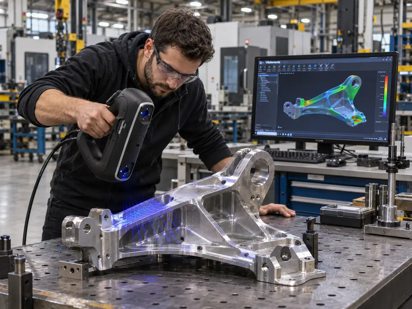

Learn how VXelements supports 3D scanning, probing, photogrammetry, mesh processing, scan-to-CAD, dimensional inspection, reporting, and legacy workflows.

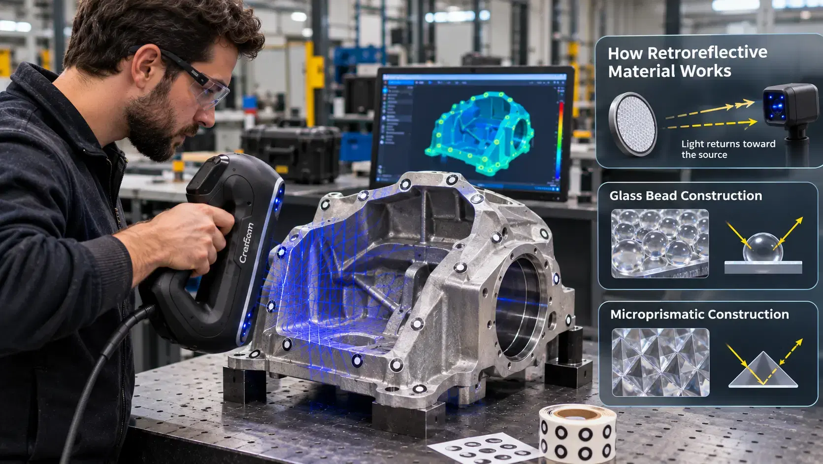
Learn how retro reflective material works, why 3D scanners use reflective targets, and how proper target placement supports tracking and accurate measurement.
Learn what metrology means in manufacturing and how dimensional inspection, calibration, traceability, uncertainty, and measurement support better quality control.

Whether you're evaluating 3D scanners, inspection software, reverse engineering workflows, or CAD modeling services, our engineering team can help identify the best solution for your application.


