Learn how VXelements supports 3D scanning, probing, photogrammetry, mesh processing, scan-to-CAD, dimensional inspection, reporting, and legacy workflows.
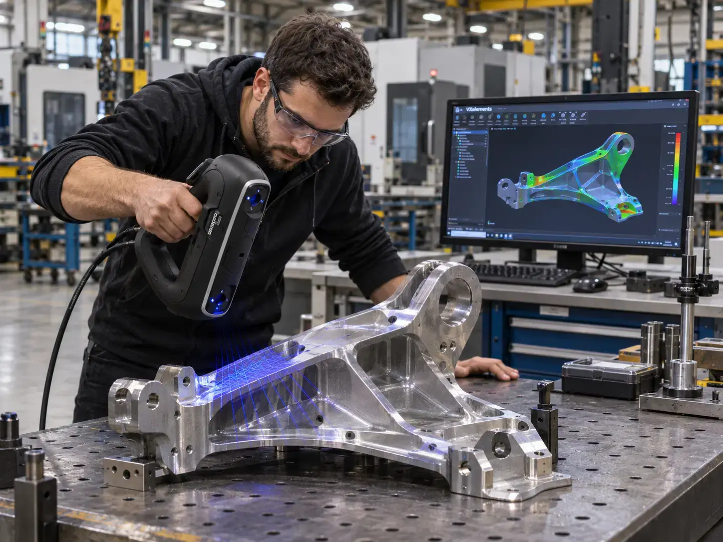
An aerospace bracket scans cleanly, but its inspection report shows a suspicious deviation near a mounting hole. Before blaming the part, the technician needs to check tracking, mesh quality, alignment, and the inspection setup. The software connecting those steps matters as much as the scanner.
VXelements was Creaform's integrated measurement platform for capturing, processing, and analyzing 3D data. Although Creaform introduced Creaform.OS and the Creaform Metrology Suite in 2025, understanding VXelements remains useful for teams operating earlier installations or reviewing established workflows.
VXscan acquired data from compatible Creaform scanners and displayed the developing mesh while the operator moved around a part. Live visualization helped reveal missed regions before the component left its fixture.
Its smart resolution functionality supported different detail levels within a scan. Operators could devote higher resolution to sharp edges and small features without treating every broad surface identically.
Mesh enhancement and scan merging also supported difficult acquisitions. A useful practice was to review overlap and tracking before merging sessions, rather than assume software could rescue poorly positioned scans.
For an automotive casting, those checks could reveal an incomplete flange or missing pocket wall while rescanning was still practical. Teams should document scanner settings, target placement, and environmental conditions alongside the project, when operators capture comparable parts across shifts. These records help explain differences before making tooling adjustments.
VXprobe supported coordinate acquisition using compatible HandyPROBE equipment. Rather than capturing an entire surface, an operator touched selected features to establish points, planes, circles, and other geometric references.
That made probing useful for accessible bore locations or datums that optical scanning could not fully capture. However, a probe still needed physical access, and measurement uncertainty depended on the complete setup.
VXshot supported photogrammetry measurements with compatible equipment. Its target-based references helped establish spatial relationships across larger components, supporting work where long-range alignment mattered.
These were different acquisition methods, not interchangeable accessories. The correct choice followed the drawing's critical features, required tolerance, and actual accessibility.
VXmodel, a complementary application module, helped turn captured geometry into useful engineering references. Its tools included mesh editing, alignment, cross-sections, and geometric entity extraction.
Imagine recreating a discontinued pump housing. A raw mesh shows its worn exterior, but a designer needs an intended flange plane, shaft axis, and mounting-hole pattern. Extracted sections and entities can guide reconstruction in CAD software.
Mesh cleanup requires restraint. Automatically filling an unscanned recess introduces estimated geometry, not a measurement. Similarly, best-fit alignment may make a damaged surface appear closer to nominal than a functional datum alignment would.
Creaform's later software offering continues this scan-to-CAD role, but feature availability depends on the edition and license. Verify the actual toolset before promising a complete editable solid model.
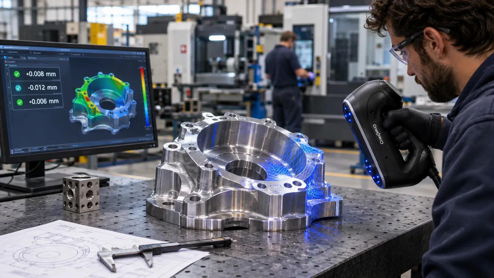
VXinspect supported comparing scanned or probed geometry against CAD, generating deviation maps, evaluating features, and preparing inspection results. The VXelements 11 release separated VXinspect into Analysis and Quality Control offerings for different inspection activities.
A color map offers a fast visual indication of surface differences. It does not independently establish acceptance. Inspectors must choose the correct datums, units, tolerance limits, and measurement decision rules.
For a welded fixture, aligning to the mounting surfaces may reveal a misplaced bracket that whole-part best fit would partially disguise. Save the alignment strategy so another shift can reproduce the result.
Inspection reports should identify what was measured, what reference was used, and which characteristics passed or failed. That context turns a vivid image into evidence a quality manager can review.
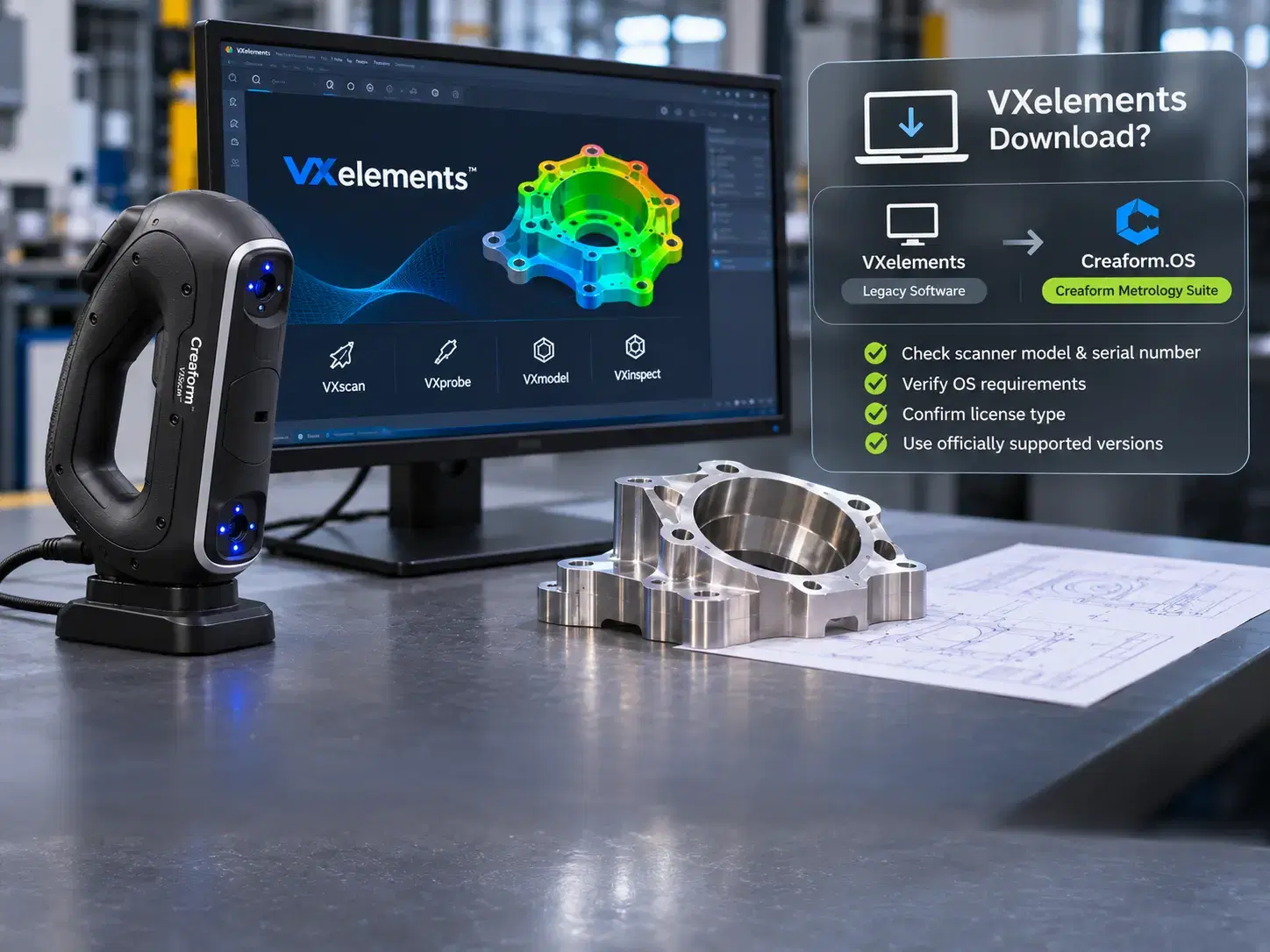
Searching for a vxelements download can lead to older installers, brochures, or viewer information. Creaform's current product direction uses Creaform.OS and the Creaform Metrology Suite, so do not assume a legacy download is appropriate for a newer scanner.
Confirm the scanner model, serial-number eligibility, operating-system requirements, license type, and supported software release with Creaform or an authorized reseller. Avoid unofficial installer mirrors, especially on computers handling proprietary manufacturing data.
The legacy VXelements Viewer was offered for reviewing 3D meshes and VXinspect reports without a full authoring workflow. Viewer availability and file compatibility should also be checked for the version your team uses.
Not as the main current branding. Creaform introduced Creaform.OS and the Creaform Metrology Suite in 2025, replacing the former VXelements offering.
VXmodel could prepare meshes and extract geometry for CAD reconstruction. An accurate parametric model still required engineering decisions and, often, work inside CAD software.
No. Software assists evaluation, but the drawing, calibration, alignment, uncertainty, and acceptance rules still govern inspection decisions.
Yes, through suitable reports and compatible viewing tools. Consistent templates and documented setups help ensure that colleagues interpret the same measurement correctly.
Bring a representative part, its CAD model, and a real inspection tolerance to your next software demonstration. Ask the operator to show live acquisition, mesh checks, alignment choices, and the resulting report.
Dynamic 3D, an authorized Creaform reseller in Allen, Texas, can help manufacturers assess compatible scanning software and measurement workflows. Schedule a demonstration centered on the features your team actually needs.
Expand your knowledge with additional resources designed to help engineers, manufacturers, and quality teams make more informed decisions.
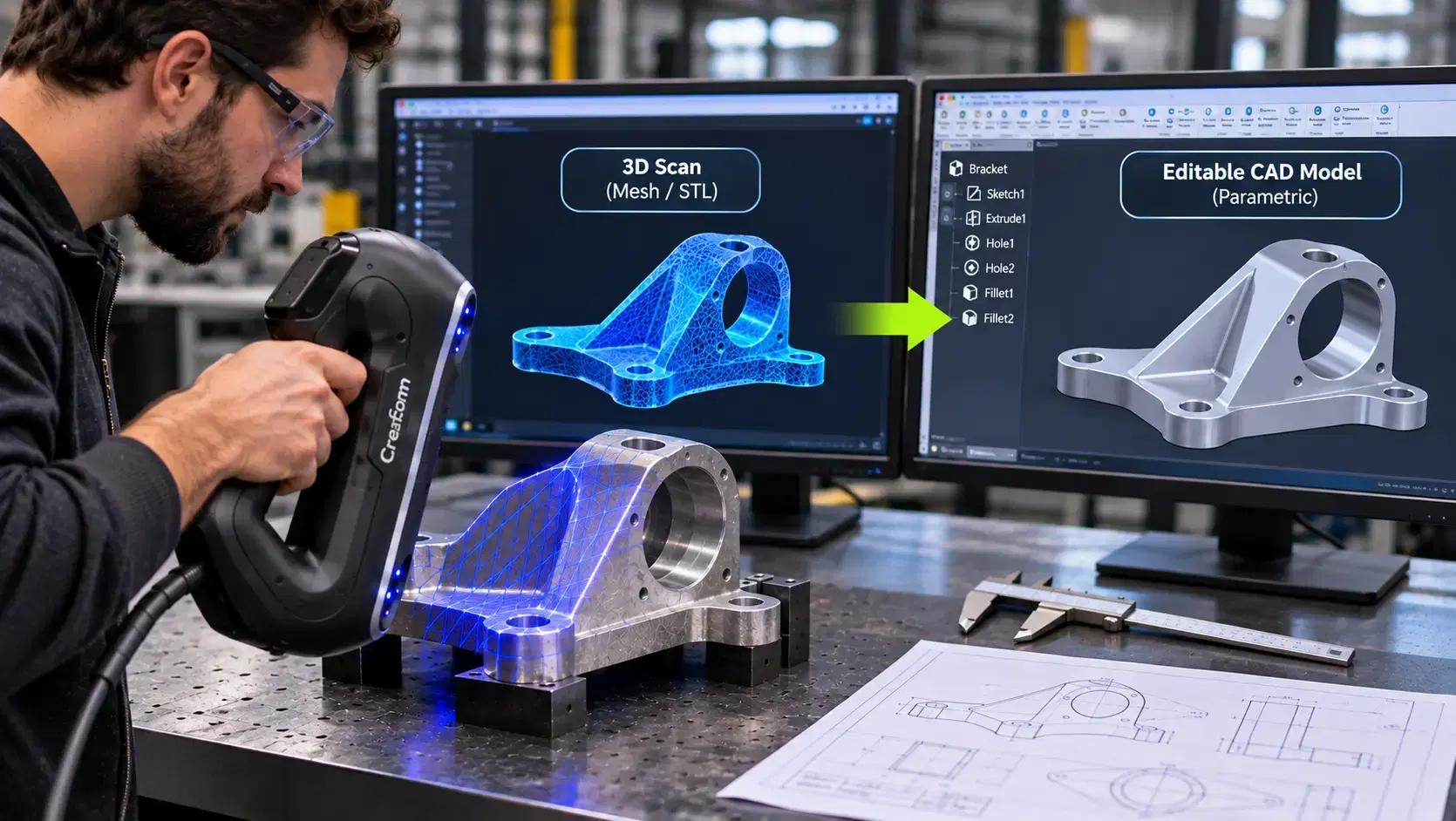

Learn how a 3D scan is converted into editable CAD using mesh cleanup, alignment, feature extraction, reverse engineering, and scan-to-CAD verification.

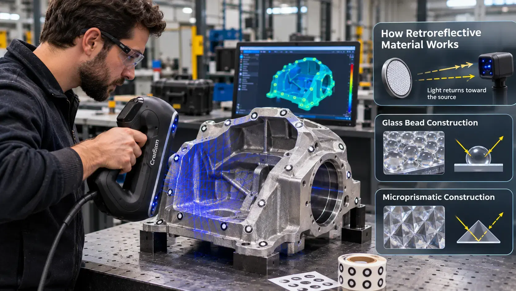
Learn how retro reflective material works, why 3D scanners use reflective targets, and how proper target placement supports tracking and accurate measurement.
Learn what metrology means in manufacturing and how dimensional inspection, calibration, traceability, uncertainty, and measurement support better quality control.

Whether you're evaluating 3D scanners, inspection software, reverse engineering workflows, or CAD modeling services, our engineering team can help identify the best solution for your application.


