Learn what metrology means in manufacturing and how dimensional inspection, calibration, traceability, uncertainty, and measurement support better quality control.
A machined shaft arrives at assembly looking identical to the approved sample. Yet its bearing fit is tight, and the production team cannot explain why. The drawing specifies a diameter of 25.000 millimeters with a tolerance of plus or minus 0.010 millimeters. Appearance cannot tell anyone whether the shaft meets that requirement. Measurement can.
That is the practical value of metrology. It turns assumptions about manufactured parts into evidence engineers can use before defects reach customers in daily production.
Metrology is the science of measurement and its application. In manufacturing, it covers the methods, instruments, reference standards, and procedures used to establish whether a component meets its specifications.
It is more than taking a reading with calipers. A useful measurement must identify what was measured, how it was measured, and how much uncertainty accompanies the result.
Consider a hole specified at 10.00 millimeters with a tolerance of 0.05 millimeters. A reading of 10.04 millimeters sounds acceptable, but the instrument's uncertainty and the inspection rule still matter. Without those details, the number alone cannot settle the decision.
Manufacturing errors become expensive as parts move downstream. A bracket drilled incorrectly might cost little to rework before assembly, but much more after installation inside a finished machine.
Dimensional inspection catches problems earlier. It also shows whether a process is drifting rather than merely identifying the occasional rejected part.
Suppose a machining line produces 200 housings per shift. Measurements that steadily approach the upper tolerance limit may indicate tool wear, thermal movement, or an unstable fixture. Investigating that trend can prevent scrap before the first part fails inspection.
Reliable results also reduce disagreements between suppliers and customers. Both sides can discuss the same drawing requirement, measurement method, and acceptance criteria instead of arguing over whose instrument is correct.
Different features require different instruments. A micrometer can check an accessible diameter quickly, while a coordinate measuring machine, or CMM, measures more complex geometric relationships using a probe.
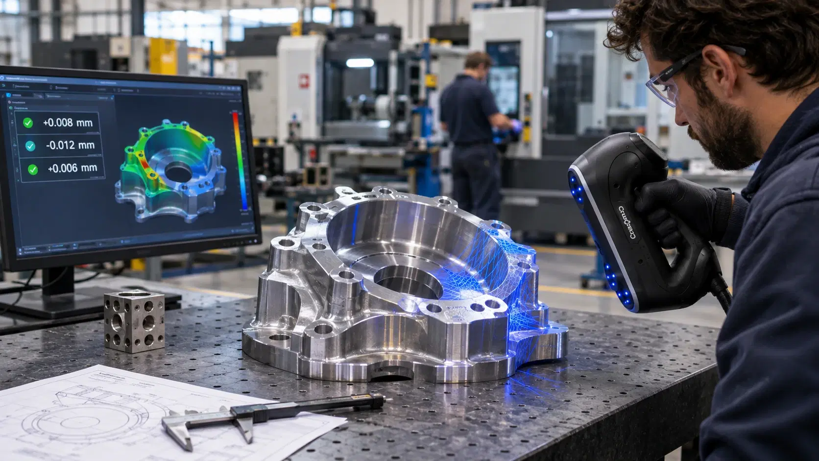
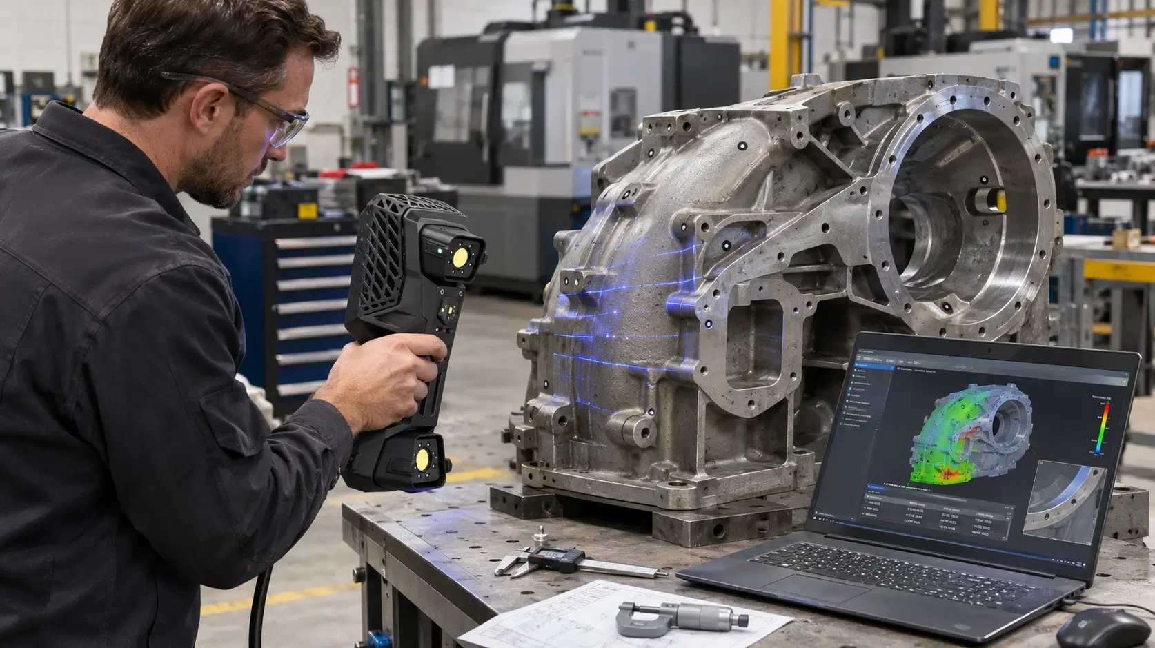
Optical scanners capture large numbers of surface points without contacting the part. Engineers can compare a resulting point cloud or mesh against a CAD model to reveal shape deviations across castings, sheet metal, and tooling.
For example, a color deviation map may show that one corner of a stamped panel sits 0.8 millimeters above the nominal surface. That result helps the team locate an issue rather than searching the entire component manually.
However, more captured points do not automatically mean better accuracy. Scanner calibration, surface properties, positioning, and inspection software all affect the usefulness of the final measurements.
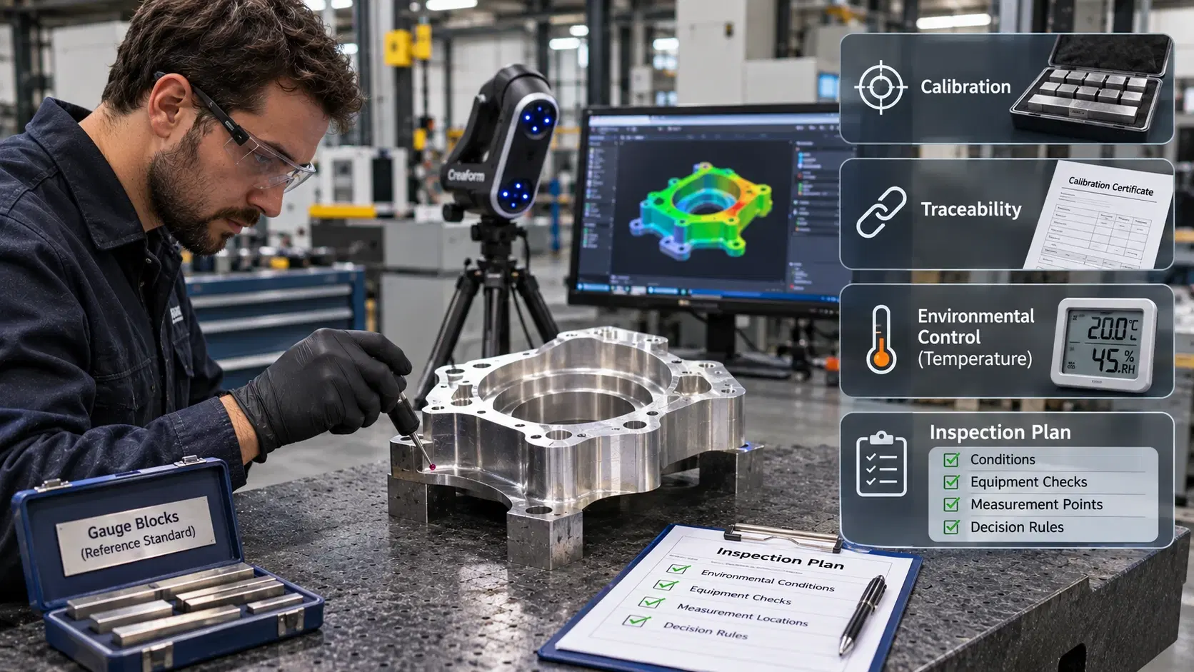
A measurement instrument needs periodic checks against appropriate references. Calibration establishes the relationship between its indication and a reference value under specified conditions. It does not automatically repair an instrument or make every future reading reliable.
Traceability connects a measurement result to recognized references through a documented, unbroken chain of calibrations. Each link contributes uncertainty, which matters when tolerances become narrow.
Temperature also deserves attention. Steel expands as it warms, so a large component measured beside a hot machine may differ from the same component measured in a controlled inspection room.
An inspection plan should therefore specify environmental conditions, equipment checks, measurement locations, and decision rules. These details help different operators reach comparable results on different shifts.
Not every factory needs to purchase a CMM or industrial scanner. Specialized metrology services can support occasional projects, oversized parts, equipment shortages, or inspections requiring skills outside the existing quality team.
A typical assignment begins with drawings, CAD files, critical dimensions, and tolerance requirements. The provider then selects suitable equipment, captures measurements, analyzes deviations, and supplies a report tied to the inspection questions.
Ask what the deliverable includes before commissioning work. A visual 3D model may help communicate geometry, but a dimensional inspection report needs clearly defined features, measured values, tolerances, and acceptance results.
For regulated or high-consequence components, discuss documented methods, traceability, uncertainty, and any customer-specific qualification requirements before approving the inspection plan.
Metrology provides the measurement principles and methods. Quality control uses measurement results, among other evidence, to decide whether products meet requirements and whether production needs correction.
Aerospace assemblies can depend on closely controlled hole positions, profiles, and fits. Reliable inspection supports conformity assessments and helps teams investigate deviations before installation.
No. Meteorology studies weather and atmospheric conditions. Metrology concerns measurement, including dimensional measurement used throughout manufacturing.
Sometimes, but not universally. Scanning works well for broad surface comparisons, while a CMM may suit particular features or tighter requirements. Select equipment based on the specified measurand and uncertainty.
Start with one part your team struggles to inspect. Identify the critical tolerance, required reporting, available access, and cost of an incorrect decision. Then compare measurement workflows against those constraints rather than shopping by scanner specifications alone.
Dynamic 3D supports manufacturers with dimensional inspection and metrology services. Talk to our team about a real component and the measurements your next production decision depends on.
Expand your knowledge with additional resources designed to help engineers, manufacturers, and quality teams make more informed decisions.
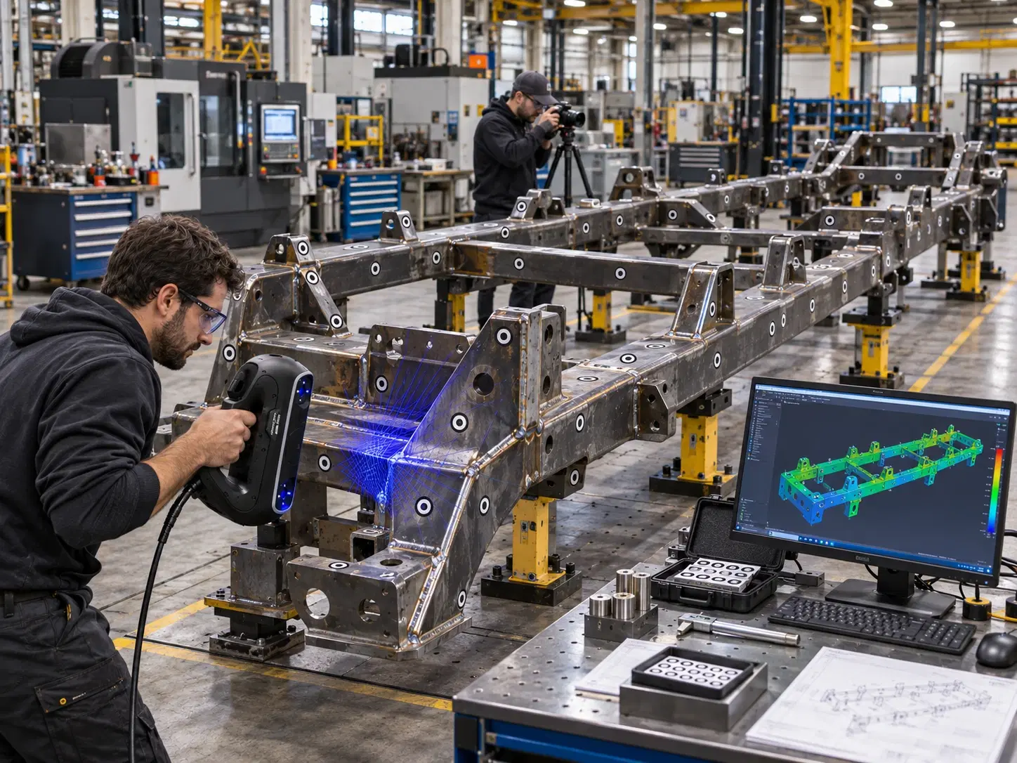

Learn how photogrammetry targets improve industrial 3D scanning accuracy by supporting large-part alignment, positioning, dimensional control, and inspection.

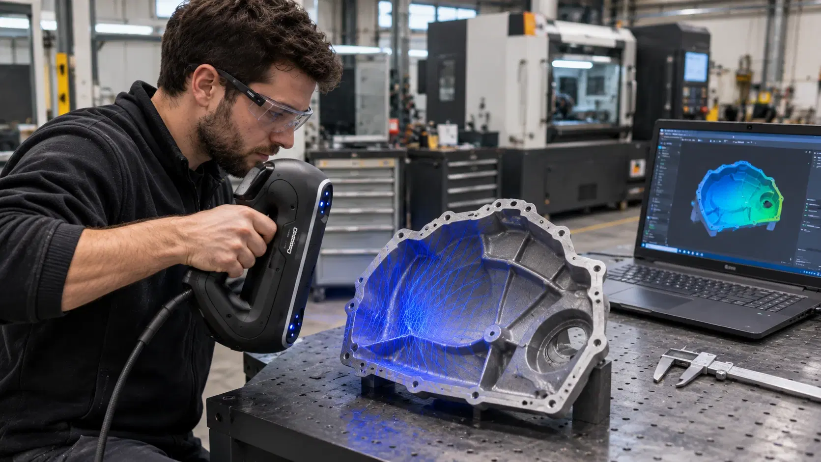
Learn how a 3 dimensional scanner captures physical geometry, creates point clouds and meshes, and supports inspection, reverse engineering, CAD, and manufacturing.
Learn how Creaform 3D scanning accuracy varies by scanner, part size, alignment, surface access, verification method, and inspection requirements in manufacturing.

Whether you're evaluating 3D scanners, inspection software, reverse engineering workflows, or CAD modeling services, our engineering team can help identify the best solution for your application.


