Learn how retro reflective material works, why 3D scanners use reflective targets, and how proper target placement supports tracking and accurate measurement.
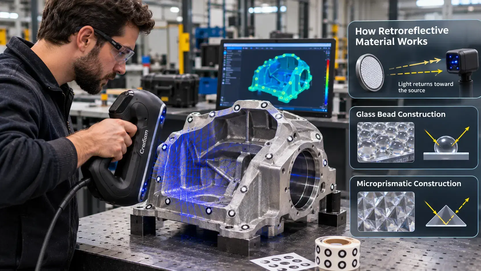
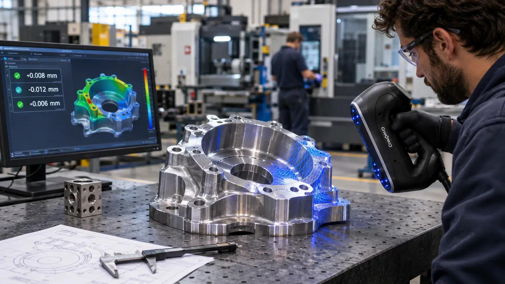
A technician moves a handheld 3D scanner across a machined housing. The software captures the surface, but how does it know where the scanner is after each movement? Small circular markers attached to the part provide an important clue.
If you are asking what is retro reflective material, the answer begins with light returning toward its source. That simple optical behavior supports everything from road signs to precise industrial measurement.
Ordinary reflection sends light in different directions depending on the surface. A mirror redirects a beam according to its angle, while a matte surface scatters light broadly. Retroreflective material sends much of the incoming light back toward the direction it arrived from.
This makes a reflective road sign appear bright to a driver whose headlights illuminate it. In industrial metrology, it helps an optical system recognize reference markers against surrounding surfaces.
Retroreflection is not perfect at every angle. Performance depends on material construction, illumination geometry, contamination, and viewing position.
A useful practical check is to observe the marker through the scanner interface while changing the viewing angle. Brightness alone is insufficient: the detection algorithm must locate the marker center consistently across successive image frames.
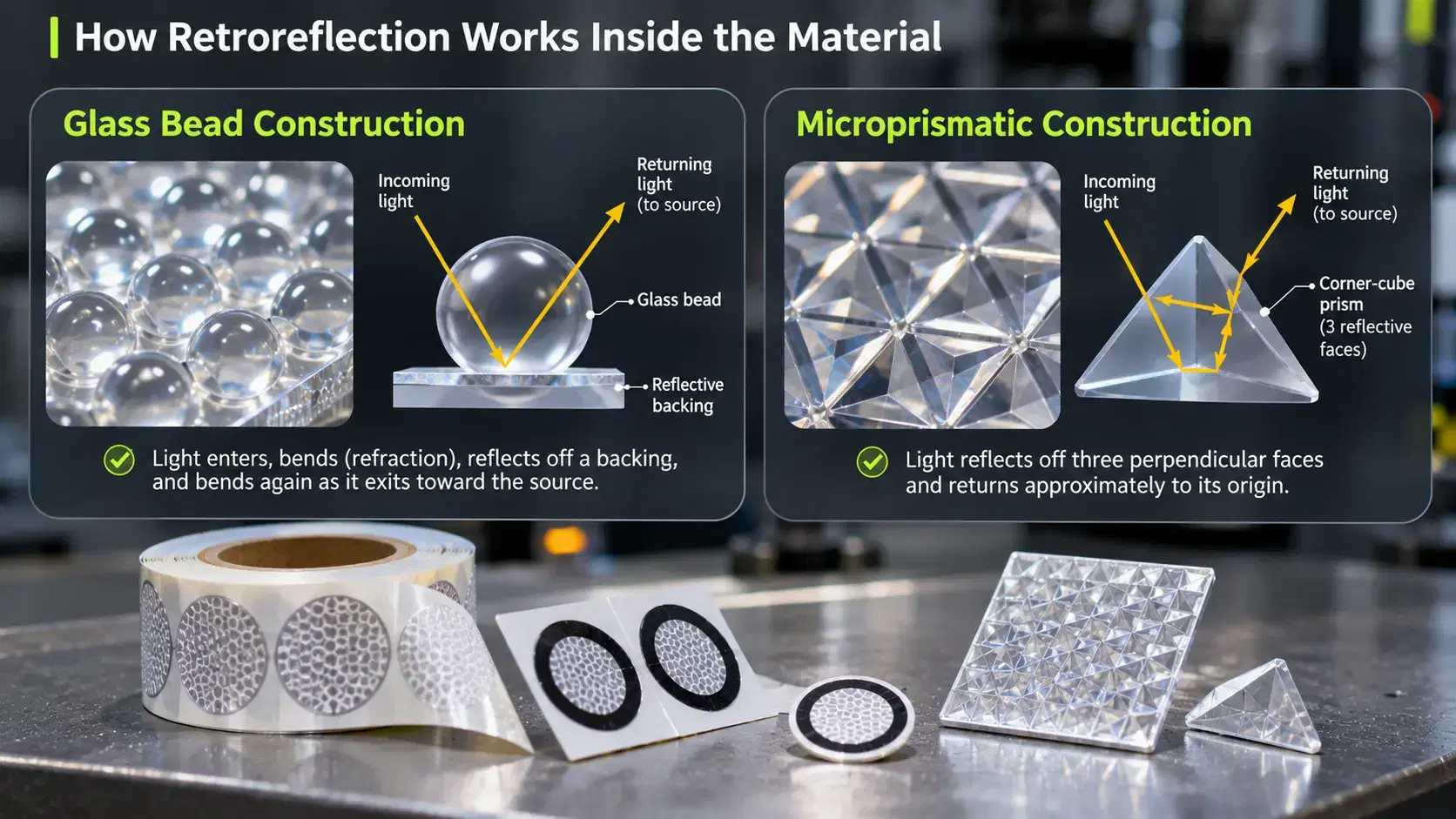
Two common designs create this effect: tiny glass beads and microscopic corner-cube prisms.
Incoming light enters a transparent bead and bends through refraction. A reflective backing redirects the light, which bends again as it exits toward the source. Thousands of beads can be embedded in flexible film or adhesive markers.
Their round geometry provides useful visibility across different approach directions, although not all incoming light returns efficiently.
Corner-cube structures contain three mutually perpendicular reflective faces. Light undergoes successive internal reflections and travels back approximately toward its origin.
Microprisms can return light efficiently, but their performance still changes with entrance angle. The design best suited to a highway sign is not automatically appropriate for a precision scanner marker.
In target-based scanning, cameras identify bright circular markers and calculate their positions relative to one another. As the operator moves around the component, overlapping target observations help the software track the scanner within a common coordinate system.
This matters on smooth castings, repetitive shapes, and large fabricated assemblies where surface geometry alone may not provide dependable alignment.
For example, consider an automotive fixture with four identical mounting brackets. Without recognizable references, successive scan views might be difficult to distinguish. A properly distributed target pattern gives the positioning system identifiable landmarks.
The scanner measures surface geometry separately. Retroreflective targets support tracking; they do not directly increase laser resolution or magically eliminate measurement uncertainty.
Begin with the scanner manufacturer's recommended target type, size, and spacing. Generic reflective tape may glow brightly but lack the precise circular geometry or optical properties needed by the system.
Distribute markers throughout the measurement area rather than clustering them in one corner. Maintain enough visible targets as the scanner moves, including around transitions and recessed regions.
Avoid placing every marker along one straight line or in a repetitive pattern. Irregular, well-spread arrangements help the software distinguish positions and orientations.
Attach targets to stable surfaces. A marker on flexible sheet metal can move relative to the intended reference, while one placed over grease may detach during inspection.
If the part cannot accept adhesive markers, suitable fixtures or surrounding supports may provide reference locations, depending on the scanner and workflow.
Dirty or damaged markers may appear dim, distorted, or inconsistent. Replace targets that peel, crease, or become covered with cutting fluid.
Poor camera angles can hide reference markers behind ribs and flanges. Plan additional passes rather than forcing the scanner to track through an obstructed view.
More targets do not always mean greater accuracy. Excessive clustering, unsuitable markers, unstable mounting, and incorrect calibration can undermine a dense network.
Check tracking feedback during capture and review the finished mesh for gaps or registration problems. For dimensional inspection, use appropriate datums, verification procedures, and uncertainty considerations before accepting results.
They can overlap, but terminology depends on the system. Many optical scanners use reflective positioning markers, while photogrammetry workflows may also require coded targets and calibrated scale references.
No. Targets identify positions for tracking. The scanner or another measurement instrument captures the hole geometry, which inspection software then evaluates.
Only if the equipment manufacturer approves them. Marker dimensions, reflectivity, and detection behavior must match the scanner's requirements.
They can help track scanning position on reflective components. Capturing the metal surface itself still depends on scanner capability, access, and surface conditions.
When evaluating a portable scanner, bring a component with repeated features, deep pockets, or difficult surfaces. Watch how consistently the system maintains tracking, then review the dimensional results rather than judging the mesh alone.
Dynamic 3D, an authorized Creaform reseller in Allen, Texas, can help manufacturers select compatible targets and scanning workflows. Request a demonstration with your own part to see how reference positioning supports inspection decisions.
Expand your knowledge with additional resources designed to help engineers, manufacturers, and quality teams make more informed decisions.
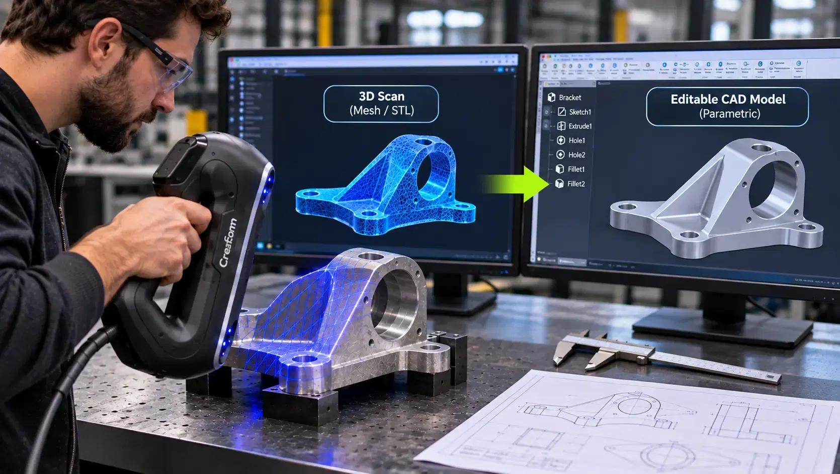

Learn how a 3D scan is converted into editable CAD using mesh cleanup, alignment, feature extraction, reverse engineering, and scan-to-CAD verification.

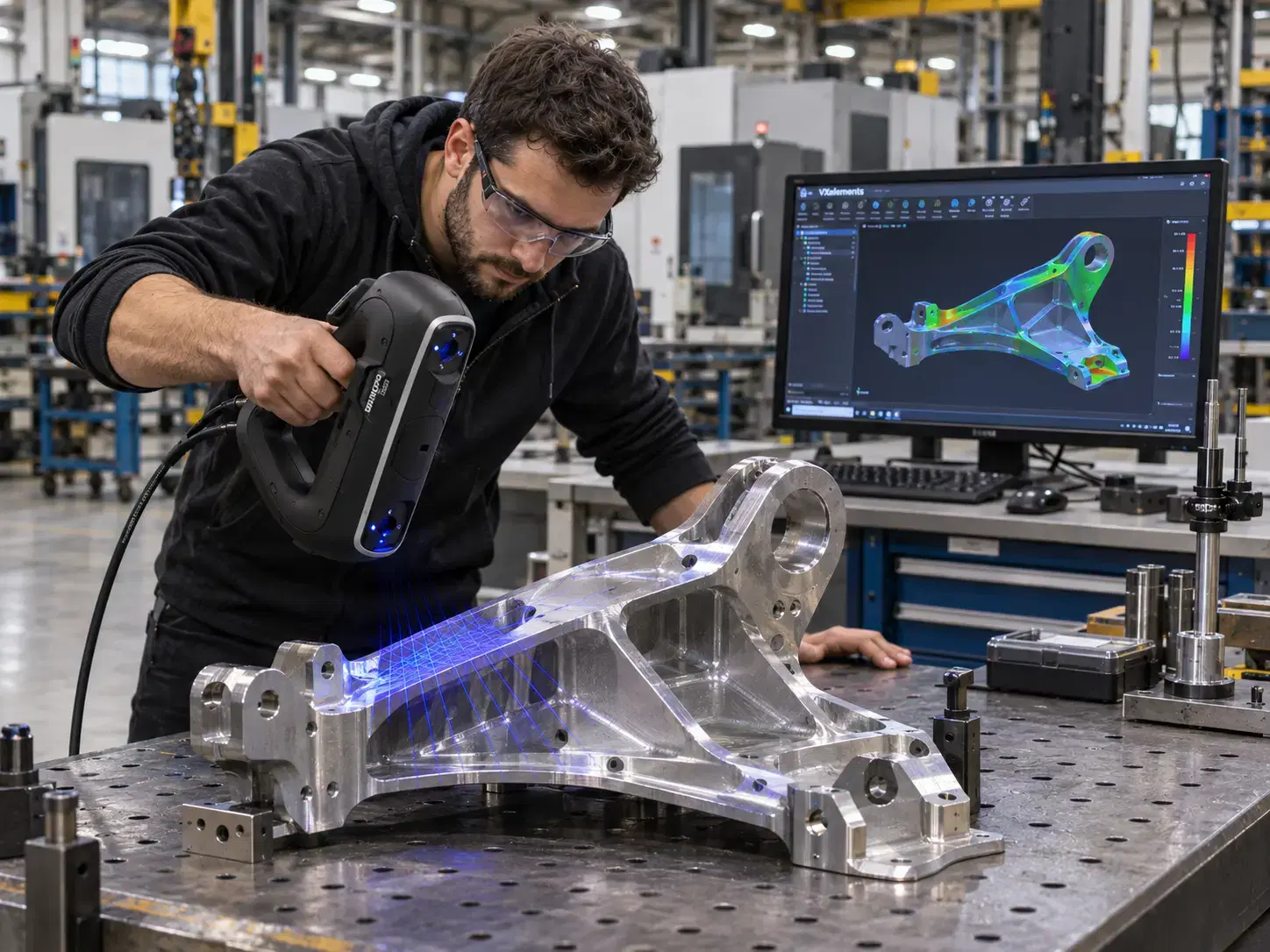
Learn how VXelements supports 3D scanning, probing, photogrammetry, mesh processing, scan-to-CAD, dimensional inspection, reporting, and legacy workflows.
Learn what metrology means in manufacturing and how dimensional inspection, calibration, traceability, uncertainty, and measurement support better quality control.

Whether you're evaluating 3D scanners, inspection software, reverse engineering workflows, or CAD modeling services, our engineering team can help identify the best solution for your application.


