Learn how a 3D scanner for reverse engineering captures real geometry, reduces guesswork, improves fit, supports scan-to-CAD, and speeds product development.
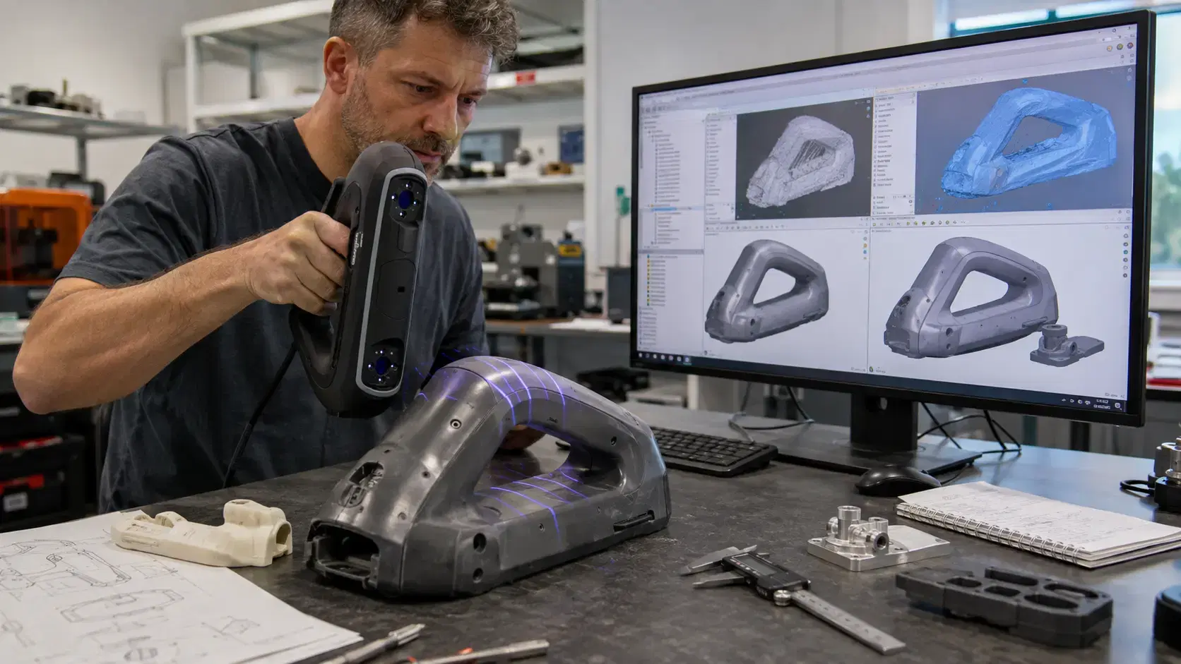
Product development often slows down when the physical part and the digital file no longer match.
A prototype may be sanded by hand. A supplier sample may arrive without CAD. A legacy component may still work, but the original drawings are missing. In those moments, teams need a fast way to move from the real object back into the design workflow.
That is where a 3d scanner for reverse engineering becomes valuable. It captures physical geometry so engineers can inspect, redesign, document, and improve products with better data.
Reverse engineering is the process of studying an existing part to understand how it was made, how it fits, and how it performs.
In product development, reverse engineering is not always about copying. Often, it is about learning from the real part and bringing that information into CAD.
A scan can help recreate missing geometry, document hand-built changes, update older files, or compare a prototype against the intended design. This gives teams a clearer starting point before they make the next version.
3D scanning captures the surface of a part and turns it into digital geometry.
The scanner collects data from many angles. Software then builds a mesh that represents the shape of the object. Engineers can use that mesh for measurement, visualization, inspection, or scan-to-CAD modeling.
This is useful because many parts are difficult to measure manually. Curved housings, cast surfaces, ergonomic grips, molded covers, brackets, fixtures, and worn components may not have simple dimensions.
Instead of measuring a few points and guessing the rest, 3D scanning gives a full-surface reference.
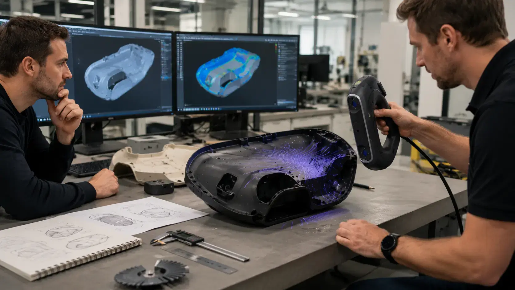
Speed is one of the biggest benefits.
Without scanning, engineers may spend hours measuring, sketching, and rebuilding shapes from partial information. Complex curves and blends can take even longer.
With scanning, the team can capture the part, review the mesh, and decide what needs to change. This helps during prototype review, supplier evaluation, product updates, and repair planning.
Faster data does not mean careless work. It means the team starts from measured geometry instead of assumptions.
Product development often fails at the interface between parts.
A cover may look correct but not close properly. A bracket may match a drawing but interfere with another component. A hand-modified prototype may work well, but the change never made it into CAD.
3D scanning helps capture those real-world fit conditions.
Engineers can compare the scan against the CAD model, check mating areas, inspect clearances, and identify where the physical part differs from the design. This makes it easier to solve fit problems before tooling, machining, or production begins.
A scan is usually the beginning, not the final engineering file.
For reverse engineering, the scan often becomes a mesh first. Then engineers use scan-to-CAD tools to rebuild clean surfaces, features, holes, planes, curves, and dimensions.
The goal is to create usable CAD, not just a digital picture. Depending on the project, the final file may support machining, fabrication, tooling, 3D printing, inspection, or future product changes.
Good scan-to-CAD work also considers design intent. A worn part should not always be copied exactly. Engineers may need to rebuild the intended shape, not the damaged condition.
Mistakes become expensive when they reach production.
If a product is built from inaccurate geometry, the result can be poor fit, rework, scrap, tool changes, delayed launches, or supplier confusion.
3D scanning and reverse engineering reduce that risk by giving teams better source data. They can validate what exists, update what changed, and document the part before making decisions.
This is especially useful for companies working with old tooling, modified prototypes, discontinued components, or parts made by outside suppliers.
A scanner is most useful when the part shape is complex or the information is incomplete.
Common examples include plastic housings, castings, machined components, sheet metal parts, custom fixtures, ergonomic models, molds, dies, adapters, guards, and replacement parts.
Scanning is also useful when design teams need to compare multiple versions of a product. They can scan the original, modified prototype, and final sample to understand exactly what changed.
Yes. The scan becomes a mesh, then engineers rebuild clean CAD using scan-to-CAD workflows.
For complex shapes, yes. Manual tools are useful for simple dimensions, but scanning captures more complete surface data.
Not always. Engineers can copy the real condition or rebuild the intended design, depending on the goal.
Manufacturing, automotive, aerospace, product design, repair, tooling, fabrication, and maintenance teams use 3D scanning and reverse engineering.
Product development improves when teams can trust the geometry they are using.
A 3d scanner for reverse engineering helps capture physical parts, reduce guesswork, solve fit problems, rebuild CAD, and move from prototype to production with more confidence.
This makes each design decision easier to explain, approve, and repeat.
Dynamic 3D can help manufacturers use 3D scanning and reverse engineering workflows to create accurate digital data for product development, inspection, repair, equipment maintenance, supplier validation, and scan-to-CAD projects across real manufacturing needs.
Expand your knowledge with additional resources designed to help engineers, manufacturers, and quality teams make more informed decisions.
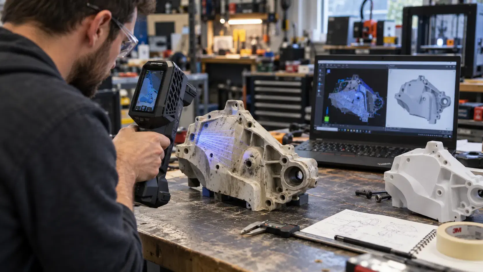

Learn how the Peel 3D scanner supports reverse engineering, product design, 3D printing, inspection, and documentation with practical handheld scanning.

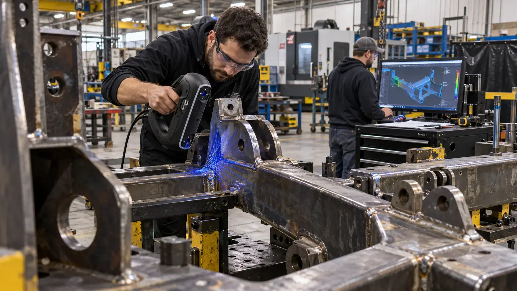
Learn how the HandySCAN 3D BLACK Series supports portable 3D scanning for inspection, reverse engineering, CAD comparison, product design, and quality control.
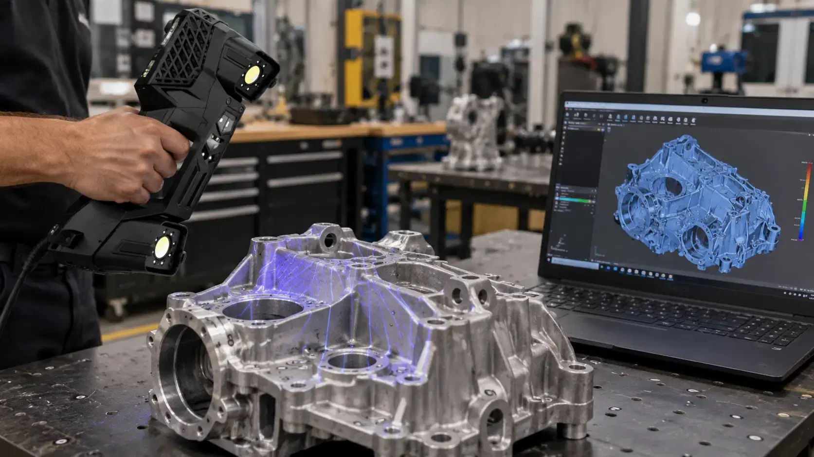
Learn how 3D scanning for reverse engineering turns physical parts into usable digital models through scanning, mesh processing, and scan-to-CAD workflows.

Whether you're evaluating 3D scanners, inspection software, reverse engineering workflows, or CAD modeling services, our engineering team can help identify the best solution for your application.


