Learn how a three-dimensional scanner captures physical geometry, creates digital scan data, and supports inspection, reverse engineering, CAD, and manufacturing.
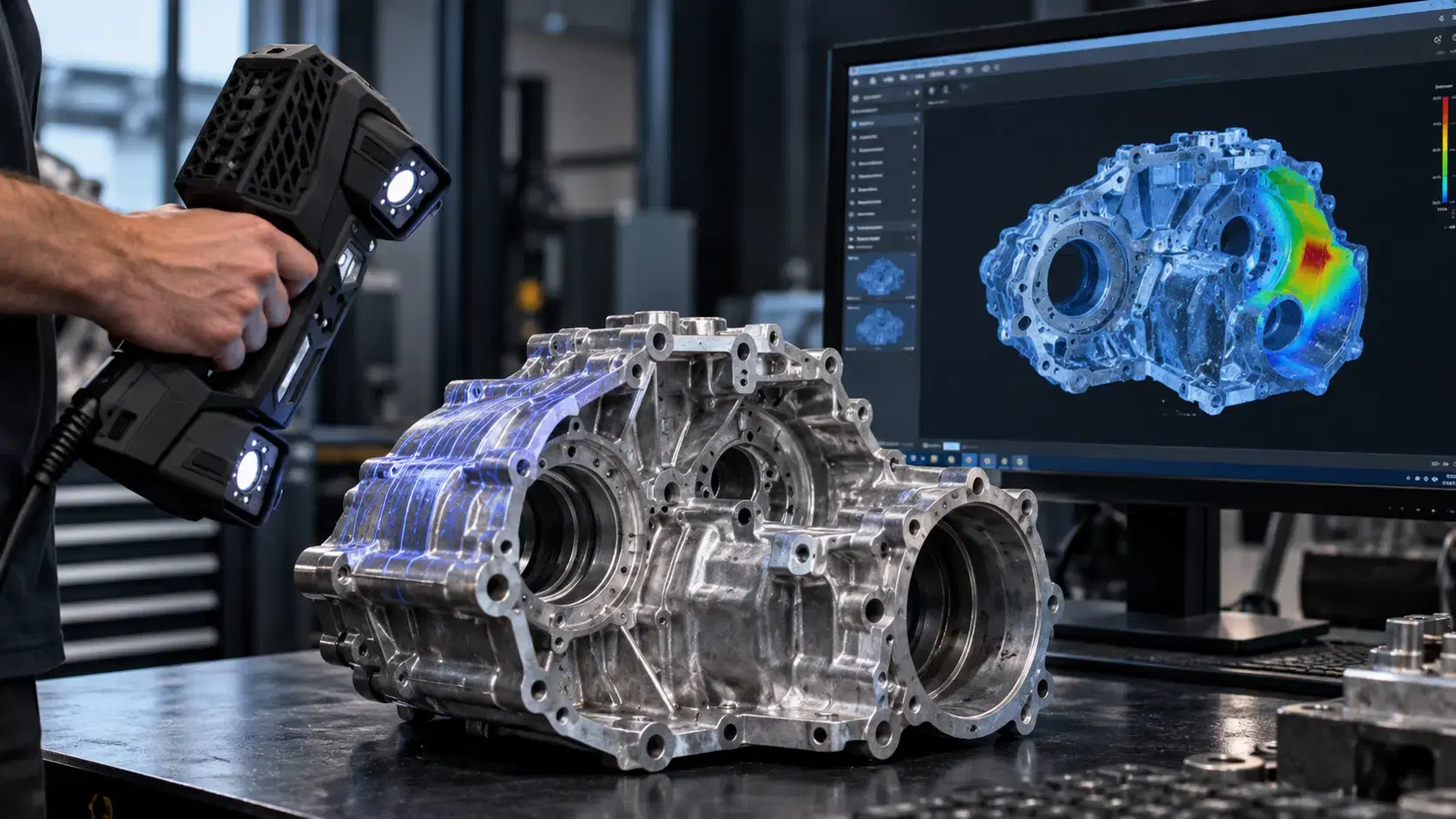
Imagine holding a replacement machine part without its technical drawing. You can measure a few distances with calipers, but capturing every curve, recess, and mounting feature takes much more effort. A three dimensional scanner offers another approach: recording visible surfaces digitally so engineers can study their shape.
The technology supports manufacturing, inspection, product development, and reverse engineering. Understanding the entire scanning process helps engineering teams confidently decide when scanning is useful and what they should expect from its results.
A three dimensional scanner is a measurement device that gathers spatial information from a physical object. Instead of producing only a flat photograph, it records positions that describe a surface in three dimensions.
Those measurements can become a point cloud, a collection of coordinates describing the captured shape. Software can connect them into a polygon mesh for visualization, comparison, or further processing.
A scan is not automatically an editable CAD model. Converting measured geometry into design features often requires additional engineering work.
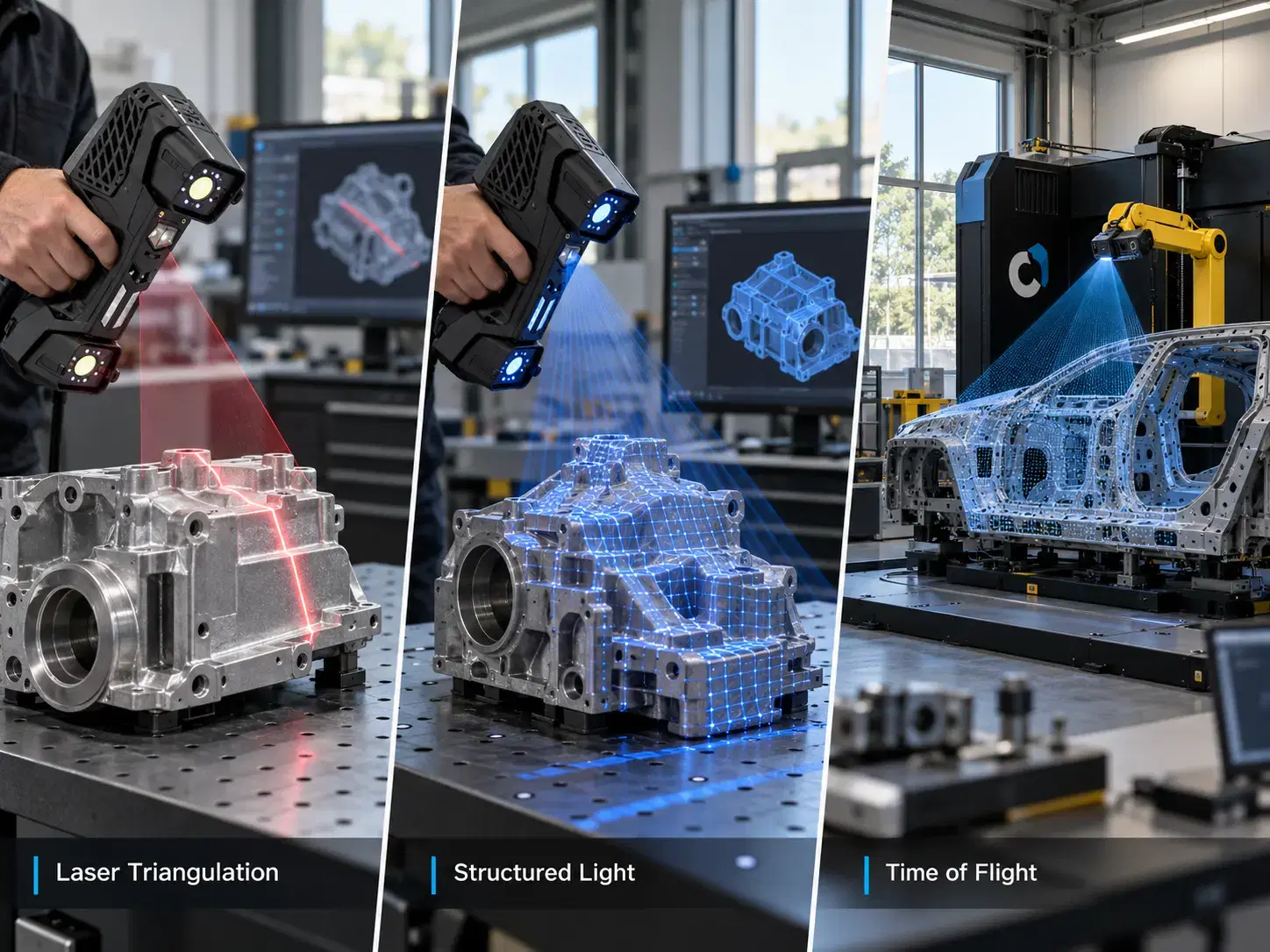
Different scanners use different measurement principles.
Laser triangulation systems project laser light onto a surface. Cameras observe its position, and software uses known geometry between the projector and sensor to calculate surface coordinates.
Structured light systems project patterns onto the object. Changes in those patterns help cameras calculate depth across many points.
Other scanners use time of flight methods to determine distance from returning light. These can be appropriate for larger environments, although equipment selection depends on range and required precision.
The most suitable method depends on the object, material, surroundings, and intended measurements.
Scanning starts with understanding the job. Determine which features matter, what tolerance the final data must support, and whether the part can be moved.
Remove loose dirt and secure the object. Reflective or transparent surfaces can challenge optical scanners, so some jobs require special settings or removable scanning spray where appropriate. Operators may place reference targets when the equipment needs them for tracking.
Preparation should never change important dimensions without being accounted for in the measurement plan.
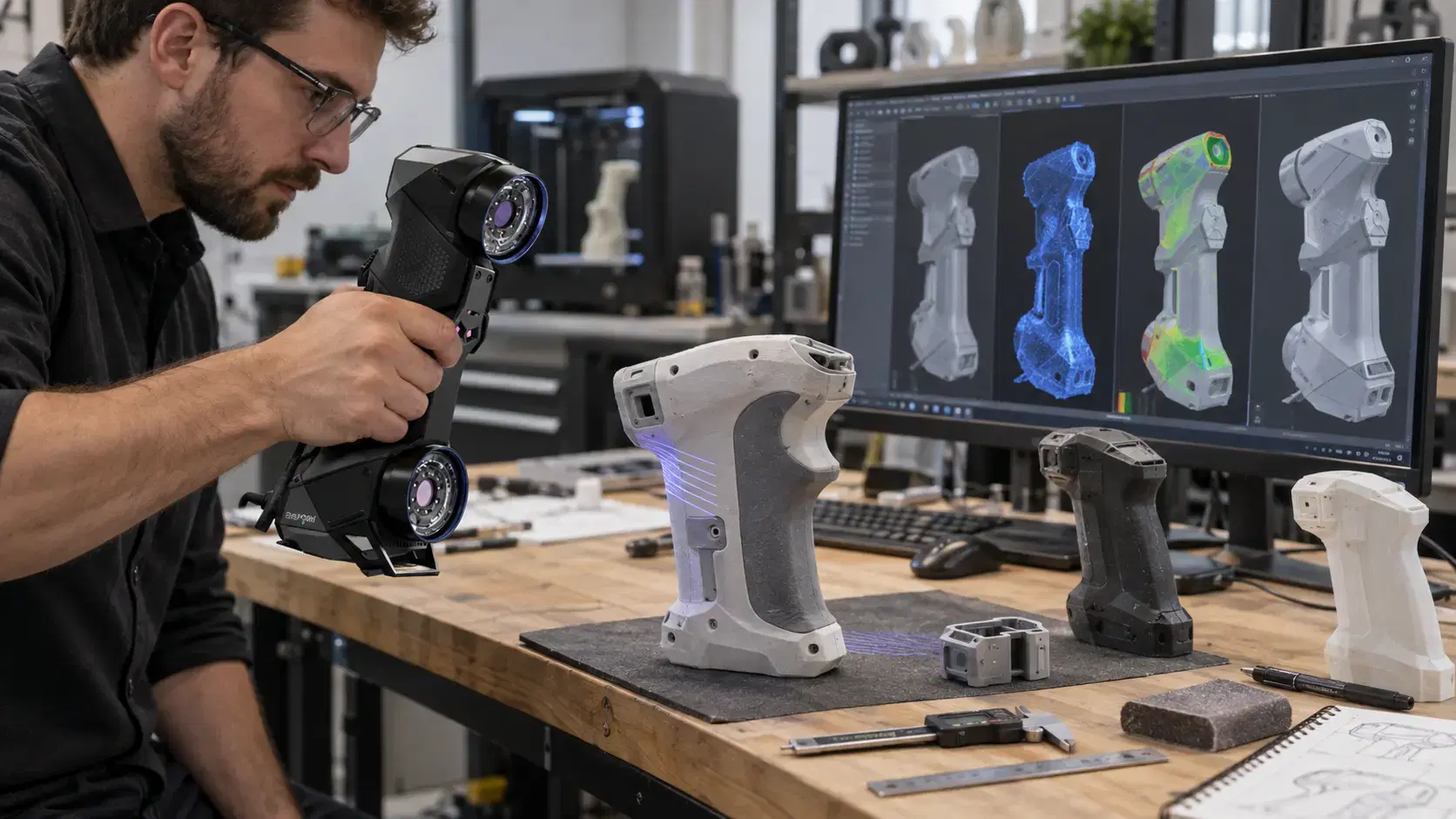
During capture, an operator moves a handheld scanner around the part or positions it inside a stationary scanning setup. The scanner records surface measurements while software tracks its location relative to the object.
A single viewpoint rarely captures everything. Undercuts, cavities, and the underside may require repositioning. Screens can show coverage and highlight areas that need another pass.
Most optical systems cannot measure surfaces hidden behind solid material. An incomplete view should not be mistaken for complete geometry.
A three dimensional scan often needs processing before anyone can use it. Software aligns separate captures, filters stray measurements, and creates a consistent point cloud or mesh.
Technicians inspect for noise, misalignment, holes, and distorted areas. They may trim unwanted background data, but should avoid inventing unmeasured geometry when filling gaps.
File formats matter. STL commonly carries triangular meshes, whereas STEP may carry reconstructed CAD surfaces or solids. Merely opening an STL inside CAD software does not create an editable feature history.
The next steps depend on the project.
For inspection, technicians can align scan data with a nominal CAD model and examine deviations. For reverse engineering, designers may rebuild planes, cylinders, holes, and freeform surfaces into editable CAD geometry.
For a prototype, a mesh may be sufficient for certain printing workflows, provided it is prepared correctly. Manufacturing may instead require dimensions, datums, and validated features.
Agreeing on deliverables early prevents a common problem: receiving an attractive model that cannot support the intended work.
Quality control: Compare produced components with design geometry to investigate shape differences and manufacturing variation.
Reverse engineering: Digitize legacy components when original models are missing, while evaluating wear before recreating parts.
Product development: Capture modified prototypes and physical mockups to guide redesign.
Maintenance: Document worn machinery, fixtures, or difficult to move equipment before repair planning.
Scanning can complement traditional metrology, but critical features may still need independent dimensional checks.
Measurement quality depends on more than the number of captured points. Scanner calibration, surface finish, lighting, working distance, environmental conditions, part movement, and alignment can all affect results.
Resolution describes detail; accuracy describes closeness to the true value. A dense mesh may still contain dimensional errors. Check the manufacturer's specifications under relevant conditions and verify critical tolerances with suitable methods.
Usually not. Multiple viewpoints or setups may be necessary to cover hidden surfaces.
Many optical scanners measure without touching the part, although preparation or reference targets may be needed.
Yes, after suitable modeling and verification where the machining workflow requires them.
No. Simple dimensions may be faster to check using traditional measurement tools.
The value of scanning lies in turning physical geometry into information engineers can trust. Choose equipment, capture methods, file formats, and verification procedures around the actual task.
Dynamic 3D helps manufacturers evaluate portable scanning, reverse engineering, dimensional inspection, and scan to CAD workflows that connect measured parts with practical engineering decisions.
Expand your knowledge with additional resources designed to help engineers, manufacturers, and quality teams make more informed decisions.
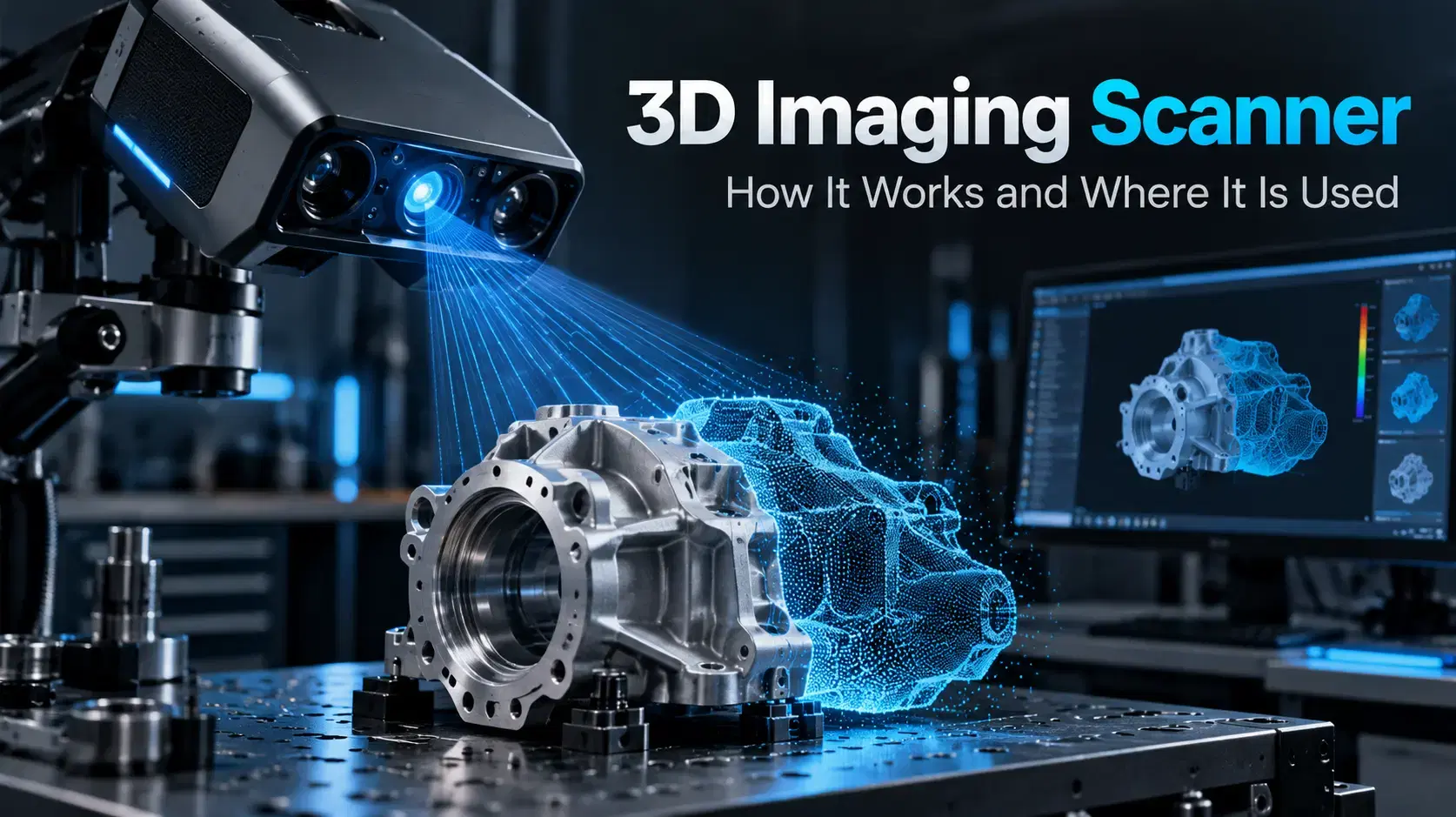

Learn how a 3D imaging scanner captures physical geometry, creates digital models, and supports inspection, reverse engineering, CAD, and industrial workflows.

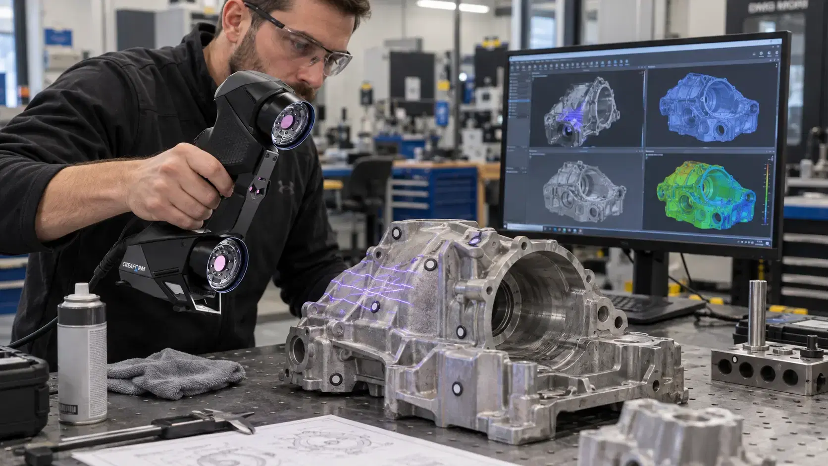

Learn how Creaform HandySCAN captures real part geometry for inspection, reverse engineering, scan-to-CAD, product development, and manufacturing workflows.
Learn when a 3D scan near me is worth it for product design, prototyping, scan-to-CAD, fit checks, and turning physical changes into useful digital data.

Whether you're evaluating 3D scanners, inspection software, reverse engineering workflows, or CAD modeling services, our engineering team can help identify the best solution for your application.


