Learn how 3D scanning for reverse engineering turns physical parts into usable digital models through scanning, mesh processing, and scan-to-CAD workflows.
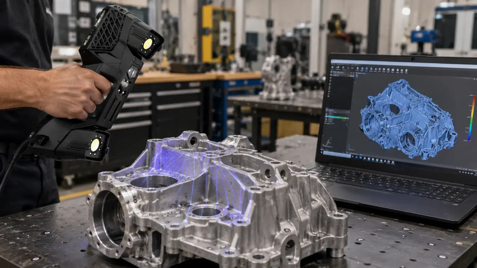
When a physical part exists but the original CAD file is missing, outdated, or inaccurate, reverse engineering becomes a practical path forward.
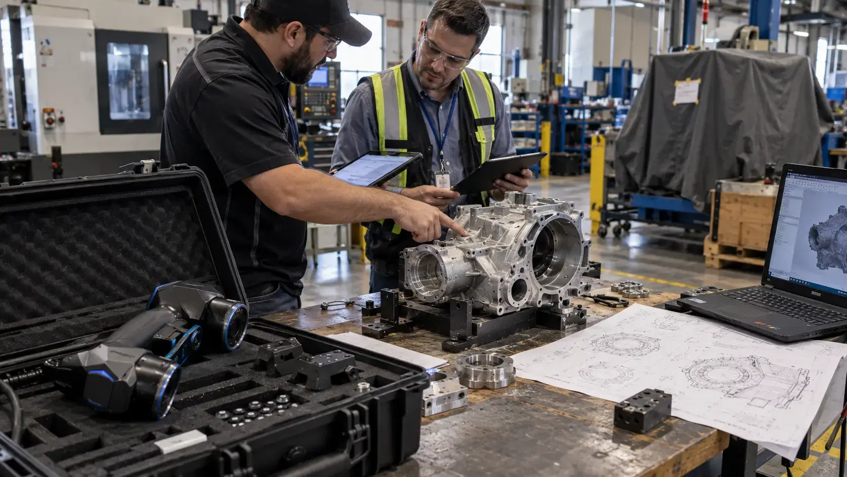
3d scanning for reverse engineering helps teams capture the real shape of a part and turn that information into usable digital data. Instead of guessing from worn drawings or measuring only a few features, manufacturers can scan the object, study the geometry, and rebuild a model that supports repair, redesign, inspection, or production.
The process is especially useful for legacy parts, prototypes, modified components, tooling, fixtures, and replacement parts that still matter to the business.
Reverse engineering is the process of studying an existing physical object to understand how it was designed, shaped, assembled, or manufactured.
In many projects, the goal is not to copy blindly. The goal is to recover useful design information. A team may need a replacement part, an updated CAD file, a better drawing, a repair plan, or a digital model for future manufacturing.
This matters when suppliers are unavailable, old files are lost, or the real part no longer matches the original documentation.
If you are asking how does 3d scanning work, the basic idea is simple.
A scanner captures the surface of a physical object by recording many points in 3D space. Depending on the system, it may use laser lines, structured light, cameras, targets, or optical tracking. As the scanner moves around the part, software collects geometry from multiple angles.
The result is usually a point cloud or mesh. A mesh represents the surface with connected triangles, creating a digital version of the scanned part.
This file becomes the foundation for measurement, comparison, and CAD rebuilding.
Before scanning begins, the part should be reviewed carefully.
Engineers or technicians look for wear, cracks, missing features, repairs, corrosion, and surface damage. This step is important because a scanner captures what exists, not necessarily what the part was intended to be.
If a part is worn or bent, copying every detail may recreate the damage. The team needs to understand which features are functional and which areas should be corrected during modeling.
Sometimes multiple samples are scanned to identify the best reference.
Preparation depends on the material and surface condition.
Dark, shiny, transparent, oily, or reflective surfaces can be harder to scan. The part may need cleaning, positioning, targets, or temporary scanning spray. Stable fixturing may also be needed so the part does not move during capture.
Good preparation improves scan quality and reduces cleanup later.
The goal is to capture enough detail for the final purpose, whether that is a simple mesh, an inspection report, or a manufacturing-ready CAD model.
During scanning, the operator moves around the part and collects geometry from different angles.
The software usually shows live feedback so the operator can see which areas are captured and which areas are missing. Hidden surfaces, deep pockets, holes, and tight corners may require extra attention.
A careful scan captures critical features, datums, mating surfaces, and overall shape. Rushing this step can create gaps that make CAD reconstruction harder.
Good scan data starts with knowing what the final model must do.
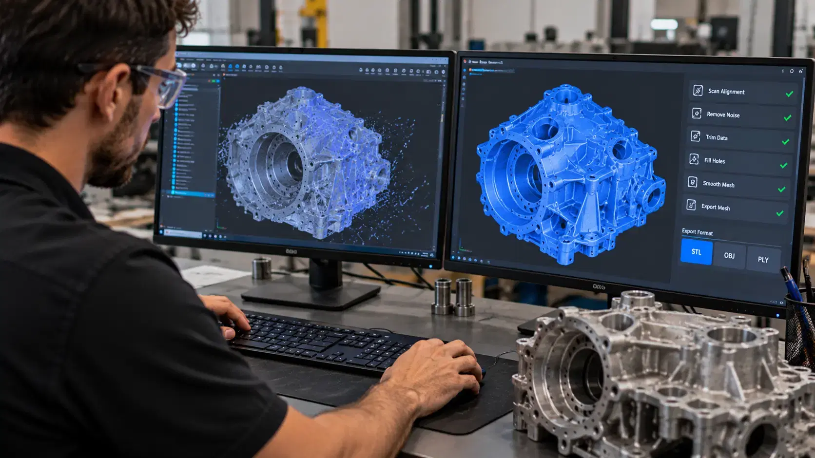
After scanning, the raw data is processed.
This may include aligning scans, removing background noise, trimming unwanted data, filling minor holes, smoothing surfaces, and exporting the mesh. Common mesh formats include STL, OBJ, and PLY.
At this stage, the data can already be useful for visualization or 3D printing, but it is not always ready for manufacturing.
A mesh is a measured surface. CAD is an editable engineering model. Reverse engineering often requires the next step.
Scan-to-CAD is the process of creating usable CAD geometry from the scan data.
Engineers rebuild planes, cylinders, holes, curves, surfaces, fillets, and features based on the mesh. The final model may be created as STEP, IGES, or native CAD, depending on the workflow.
This step requires engineering judgment. The model should reflect the intended function, not every scratch or worn edge.
A good CAD model can support machining, 3D printing, tooling, documentation, inspection, and future design changes.
Most parts can support CAD reconstruction, but complexity, damage, surface condition, and accuracy requirements affect the workflow.
For complex shapes and missing CAD, scanning gives much more surface information. Manual tools are still useful for critical dimensions.
Common outputs include STL, OBJ, PLY, STEP, IGES, native CAD files, drawings, and inspection reports.
It should not. Worn or damaged areas should be reviewed and corrected when the functional design is rebuilt.
3d scanning for reverse engineering gives manufacturers a clear way to recover design data from real objects.
The process connects inspection, scanning, mesh processing, scan-to-CAD modeling, and engineering review so teams can move from a physical part to a reliable digital model.
Dynamic 3D can help teams use 3D scanning, reverse engineering, scan-to-CAD, dimensional inspection, and Creaform-based workflows to recreate parts, support repairs, update documentation, and build better manufacturing data for real production needs today.
Expand your knowledge with additional resources designed to help engineers, manufacturers, and quality teams make more informed decisions.
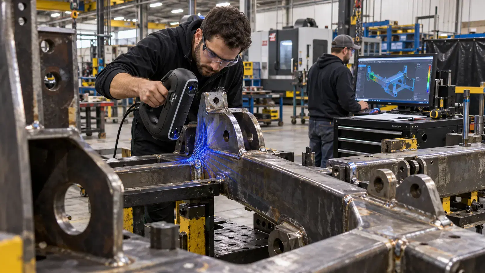

Learn how the HandySCAN 3D BLACK Series supports portable 3D scanning for inspection, reverse engineering, CAD comparison, product design, and quality control.

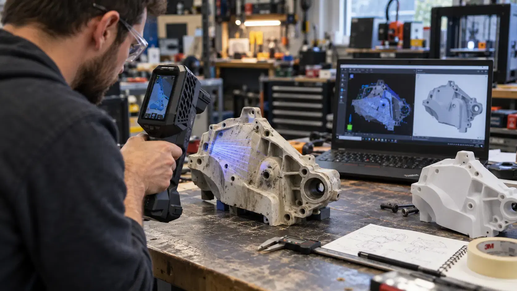
Learn how the Peel 3D scanner supports reverse engineering, product design, 3D printing, inspection, and documentation with practical handheld scanning.
Learn whether 3D scanners are illegal, what legal risks can arise, and how permission, privacy, IP, contracts, and responsible data use affect scanning projects.

Whether you're evaluating 3D scanners, inspection software, reverse engineering workflows, or CAD modeling services, our engineering team can help identify the best solution for your application.


