Learn how Creaform 3D scanning accuracy varies by scanner, part size, alignment, surface access, verification method, and inspection requirements in manufacturing.
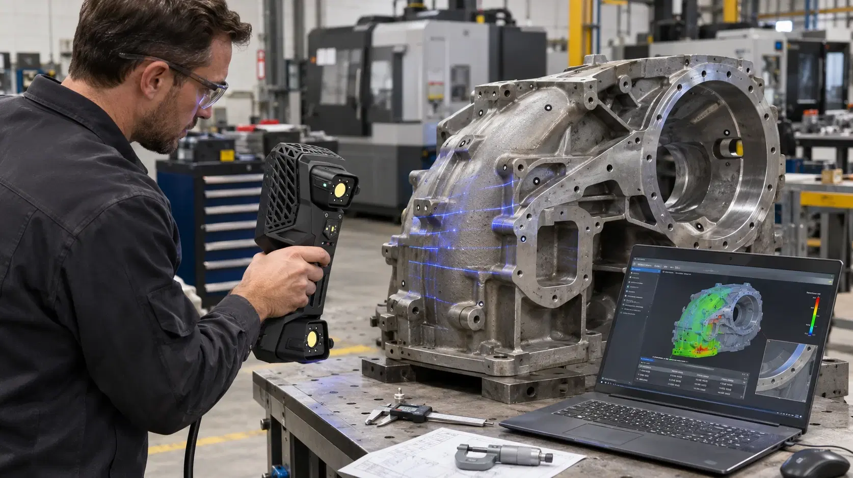
A turbine housing looks smooth until inspection reveals an uneven flange. A molded component fits one assembly but causes interference in another. In both cases, manufacturers need reliable measurements that support decisions.
Creaform 3D scanning can capture complicated surfaces and reveal geometric differences, but accuracy depends on the scanner, part size, inspection setup, and evaluation method. Understanding those variables is essential before deciding whether a scan meets engineering tolerances.
Creaform offers different scanners for different measurement tasks. Its HandySCAN BLACK Elite has a published accuracy of 0.025 mm, while the HandySCAN MAX EVO Elite lists 0.075 mm for larger components.
The MetraSCAN BLACK+ Elite also lists 0.025 mm accuracy, with separate volumetric specifications for its tracking volume. These figures come from defined test methods, not promises that every hole, edge, and inaccessible feature will be measured within the same number.
Always check the exact model and configuration. A manufacturer's specification is a starting point for planning, not a substitute for verifying your part.
Three terms often get confused.
Accuracy describes how closely a measurement approaches its actual value. Resolution concerns how finely the system records surface detail. A dense mesh can therefore look excellent while containing measurement errors.
Volumetric accuracy considers performance across the size of the measured object or working volume. This becomes especially important for long frames, large castings, and assemblies with features far apart.
For example, the HandySCAN BLACK Elite lists volumetric accuracy as 0.020 mm plus 0.040 mm per meter. Engineers should calculate the applicable specification for their part size and compare it against drawing tolerances, rather than quoting the smallest headline figure.
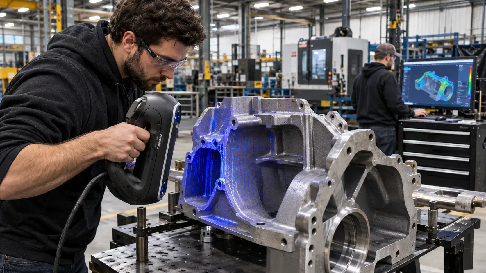
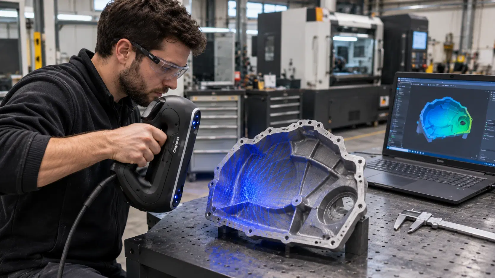
A Creaform laser scanner projects laser lines across accessible surfaces. Cameras observe those lines, and software calculates three-dimensional coordinates as the operator moves around the part.
Depending on the system, positioning may rely on reference targets or an external optical tracker. Tracking allows measurements from different viewpoints to be combined into one model.
The resulting point cloud or mesh represents captured surface geometry. Software can then align it with CAD for inspection or help engineers reconstruct design features.
Creaform scanning remains a line-of-sight process. Deep bores, hidden passages, and blocked surfaces may require repositioning, probing, or another measurement technology.
A colorful deviation map can appear convincing even when the comparison is wrong.
A best-fit alignment spreads differences across a surface to achieve a mathematical match. That may be appropriate for certain shape studies, but it can hide a displaced mounting feature.
For functional inspection, align to engineering datums or specified mounting references whenever the drawing requires them. Then evaluate hole locations, flatness, profiles, and clearances against their assigned tolerances.
Record how the alignment was performed so another inspector can reproduce the conclusion.
Broad surface coverage is a strength of optical scanning. It helps inspectors find warping, casting deviations, and distributed shape changes that individual caliper measurements might miss.
However, tight bore tolerances, inaccessible internal features, or critical mating dimensions may still require probing, gauges, or a coordinate measuring machine.
Rather than asking whether a scanner replaces traditional inspection, ask which combination of tools provides trustworthy evidence for the features that matter most.
Build verification into the inspection plan. Confirm the scanner is maintained and qualified according to manufacturer guidance. Measure suitable reference artifacts when necessary, and repeat selected features to check consistency.
Compare scan findings with independent measurements on critical dimensions. Review uncertainty when results sit close to tolerance limits, and document surfaces that could not be captured reliably.
The final report should distinguish measured geometry, CAD alignment, inferred features, and genuine out-of-tolerance conditions. A detailed mesh alone is not evidence that the finished component passes inspection.
Yes, when the selected system, setup, and verification method suit the casting's features and tolerances.
Not always. Suitable equipment and preparation can help, although finishes and geometry still affect capture.
No. Published specifications reflect defined tests; actual suitability depends on measurement conditions and feature requirements.
Optical scanners measure visible surfaces. Hidden voids and subsurface defects require other inspection methods.
Often, but reconstructed CAD must still account for wear, design intent, and verified functional dimensions.
Creaform 3D scanning can provide detailed, metrology-oriented surface measurements, including on challenging industrial parts. The useful question is whether the workflow supports the tolerances your product requires.
Dynamic 3D helps manufacturers compare Creaform scanners, evaluate inspection requirements, and build scanning and reverse engineering workflows around real production challenges.
Expand your knowledge with additional resources designed to help engineers, manufacturers, and quality teams make more informed decisions.
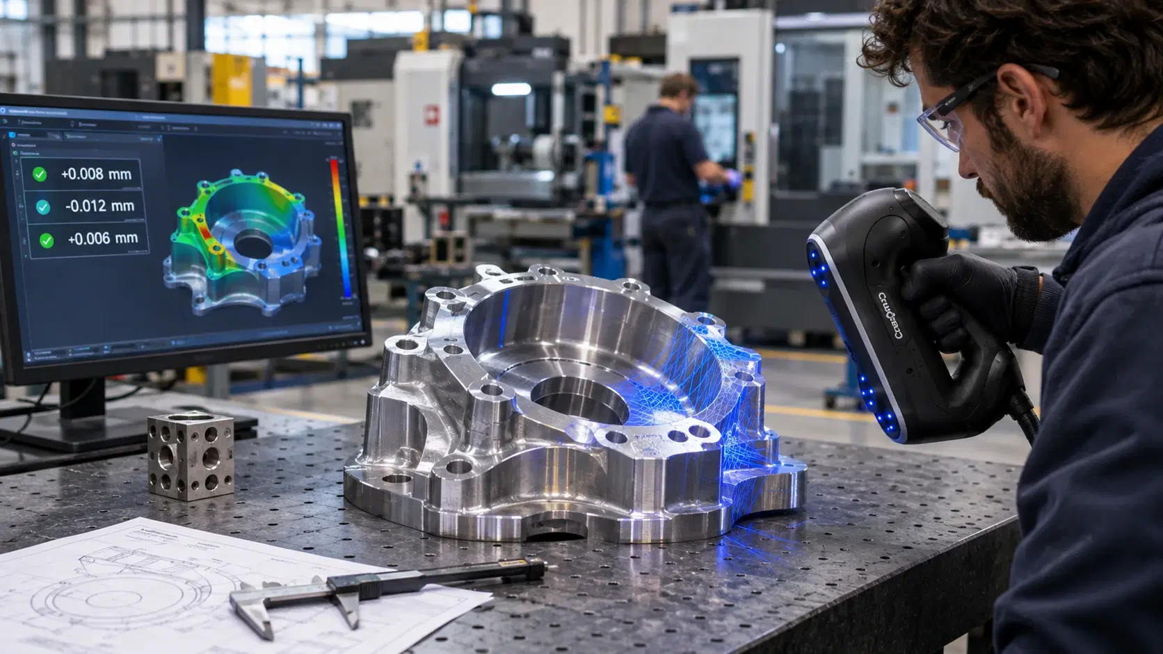

Learn what metrology means in manufacturing and how dimensional inspection, calibration, traceability, uncertainty, and measurement support better quality control.

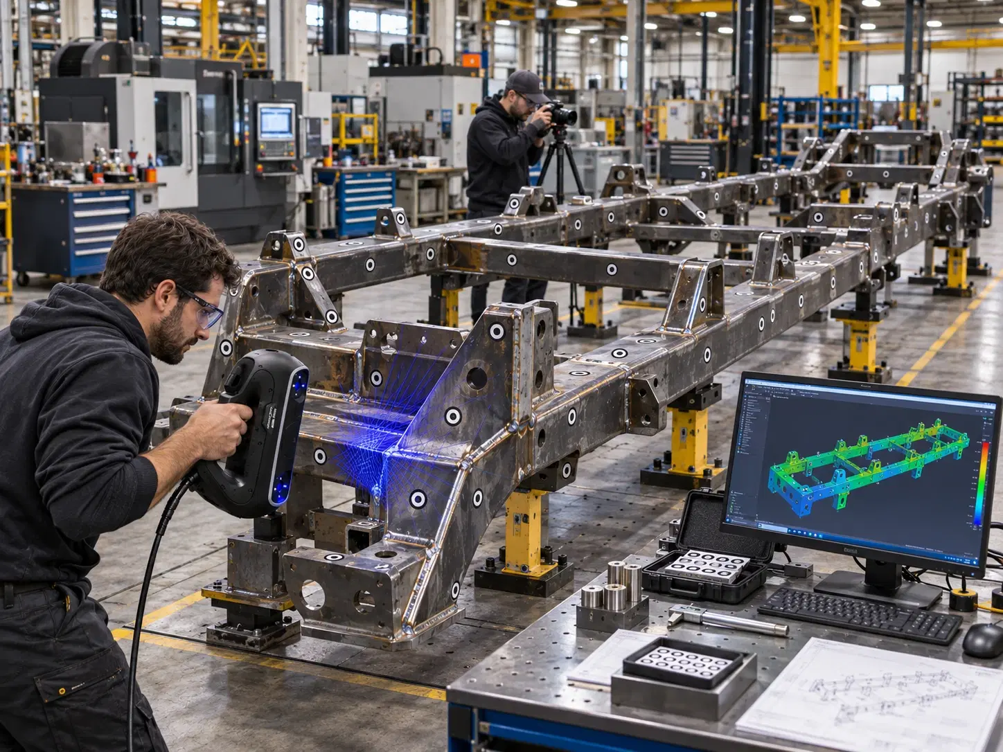
Learn how photogrammetry targets improve industrial 3D scanning accuracy by supporting large-part alignment, positioning, dimensional control, and inspection.
Learn how a 3 dimensional scanner captures physical geometry, creates point clouds and meshes, and supports inspection, reverse engineering, CAD, and manufacturing.

Whether you're evaluating 3D scanners, inspection software, reverse engineering workflows, or CAD modeling services, our engineering team can help identify the best solution for your application.


