Learn how a handheld scanner 3D captures real objects, creates digital geometry, and supports inspection, reverse engineering, 3D printing, and scan-to-CAD.
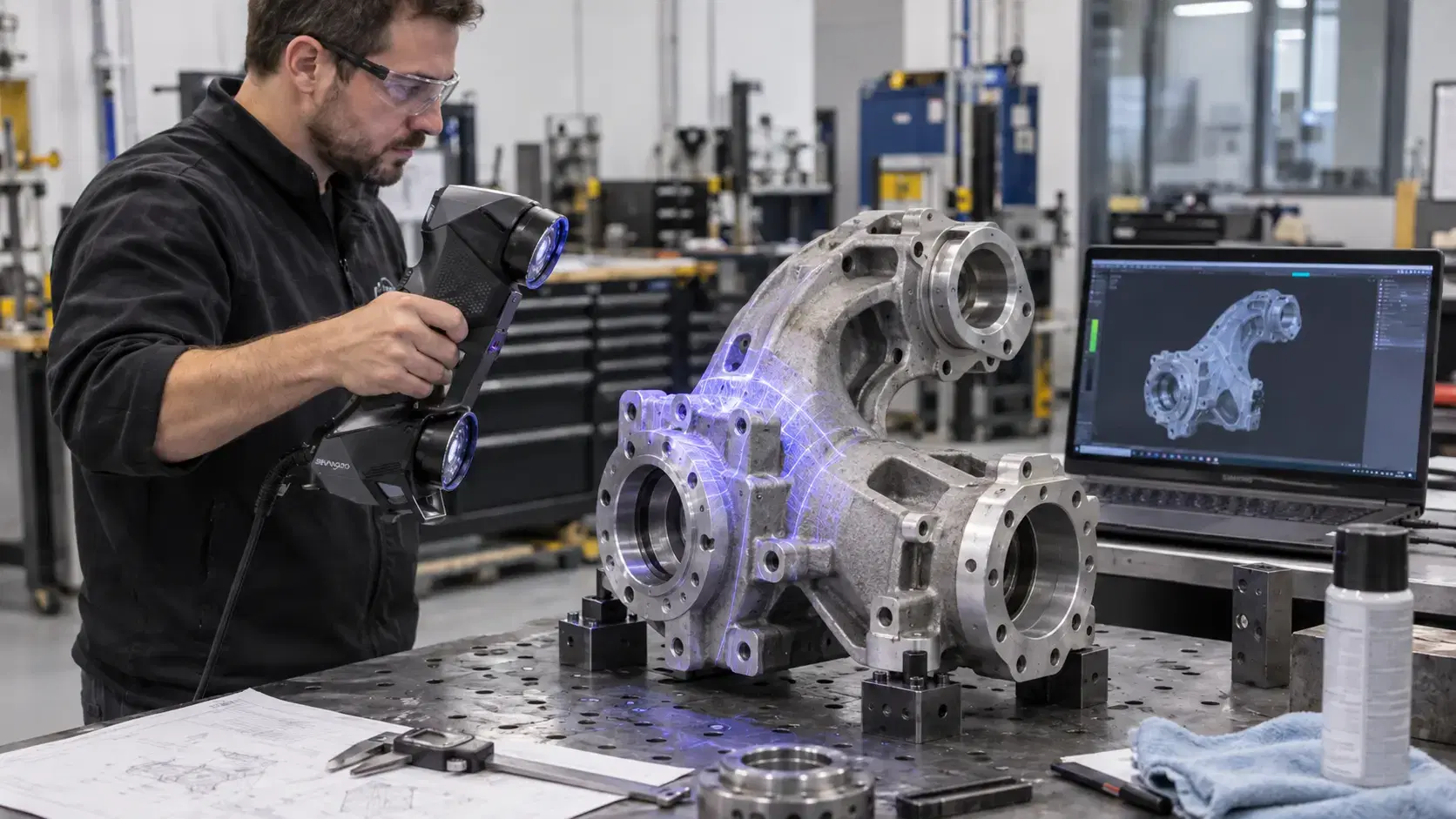
A part can look simple until you need to capture every curve, edge, hole, and surface.
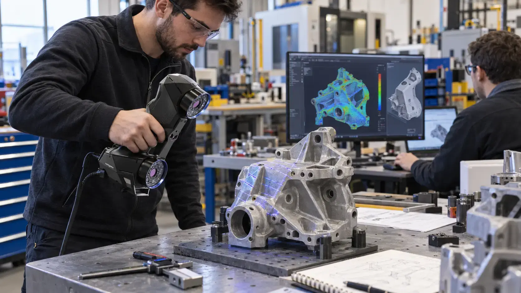
That is where a handheld scanner 3d becomes useful. Instead of moving the part into a fixed inspection setup, the operator moves the scanner around the object and captures digital geometry from different angles.
For manufacturers, designers, repair teams, and product developers, this makes physical parts easier to measure, document, inspect, reverse engineer, and turn into usable digital files.
A handheld scanner 3D is a portable device used to capture the shape of a physical object.
The scanner may use laser lines, structured light, cameras, optical tracking, targets, or surface features to understand position and geometry. As the operator moves around the part, the system records thousands or millions of surface points.
Software then uses that data to create a digital mesh. The mesh can show the actual shape of the object, including curves, edges, worn areas, and surface details.
This is different from taking photos. A camera records appearance. A 3D scanner records measurable shape.
If you are asking how do hand scanners work, the basic process starts with light and measurement.
The scanner projects light onto the surface or observes the surface through built-in sensors. Cameras inside the scanner read how that light changes across the object. Software calculates the location of many points in 3D space.
As more angles are captured, the software connects those points into a complete shape. The operator watches live feedback on the screen to see which areas are covered and which areas need more scanning.
This live feedback helps reduce missed details and makes scanning more practical for real parts.
People sometimes use the phrase handy scanner when they mean a portable handheld 3D scanner.
These systems can capture many types of parts, including plastic housings, castings, sheet metal, brackets, tooling, ergonomic models, molds, covers, fixtures, and replacement components.
They are especially helpful when the part has complex surfaces that are difficult to measure manually. A caliper may confirm one width, but it cannot show full surface warp, shrink, twist, or wear.
A scan gives the team a more complete digital reference.
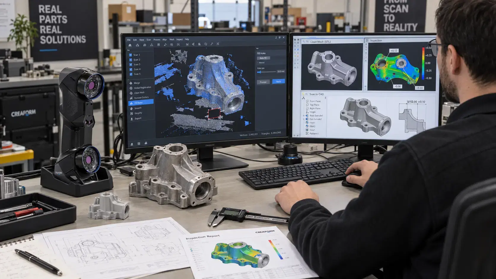
The scan is only the first step.
After capture, the data may need cleanup, alignment, trimming, hole filling, and export. The final output depends on the project.
For 3D printing, the team may need an STL or OBJ mesh. For inspection, they may need a CAD comparison report with color maps and measurements. For reverse engineering, they may need scan-to-CAD work that creates STEP, IGES, or native CAD files.
This is why the final deliverable should be defined before scanning begins.
Handheld scanning is powerful, but it still needs the right process.
Shiny, transparent, dark, oily, or reflective surfaces can be harder to capture. Some parts may need cleaning, targets, temporary scanning spray, or better lighting.
Operator skill also matters. Good results depend on proper distance, smooth movement, full coverage, correct alignment, and knowing which features matter most.
A fast scan that misses critical areas can create more work later. A careful scan matched to the right output saves time.
The best handheld scanning workflow starts with the question the data must answer. A design team may care about surface shape and fit. A quality team may care about deviation from CAD. A maintenance team may care about worn areas and replacement part geometry.
Choosing the right workflow means matching the scanner, software, preparation, and deliverable to that goal. It also means avoiding unnecessary complexity when a simpler file is enough. That planning keeps projects clearer before quoting, scanning, processing, and final engineering review later.
Yes. The scan becomes a mesh first, then engineers can use scan-to-CAD workflows to rebuild usable CAD geometry.
Yes, when the scanner, setup, software, and operator process match the required tolerance and reporting needs.
Yes, many handheld systems are useful for larger parts, especially when portability and shop-floor access matter.
For complex shapes, full-surface data, and missing CAD, yes. Manual tools still work well for simple dimensions.
A handheld scanner 3d helps teams capture physical parts without relying only on limited manual measurements.
It supports inspection, reverse engineering, product development, 3D printing, repair, and documentation by turning real objects into digital geometry.
Dynamic 3D can help manufacturers choose handheld 3D scanning, inspection, reverse engineering, and scan-to-CAD workflows that match real parts, tolerances, and production goals.
Expand your knowledge with additional resources designed to help engineers, manufacturers, and quality teams make more informed decisions.
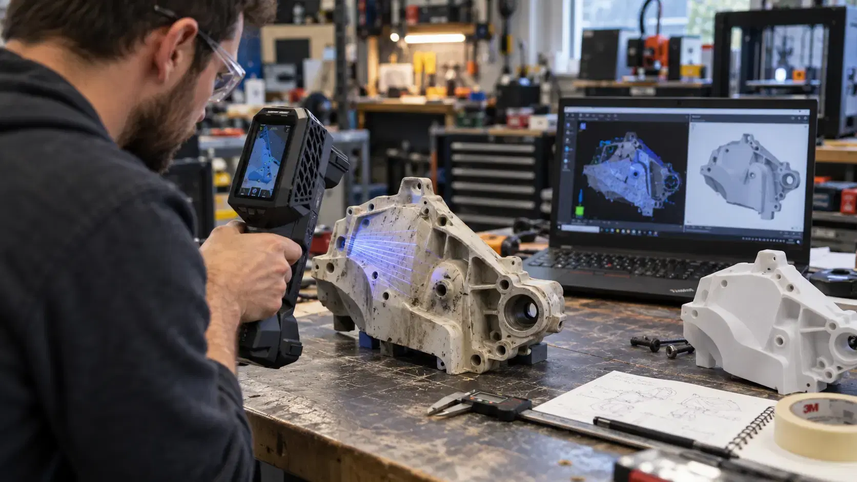

Learn how the Peel 3D scanner supports reverse engineering, product design, 3D printing, inspection, and documentation with practical handheld scanning.

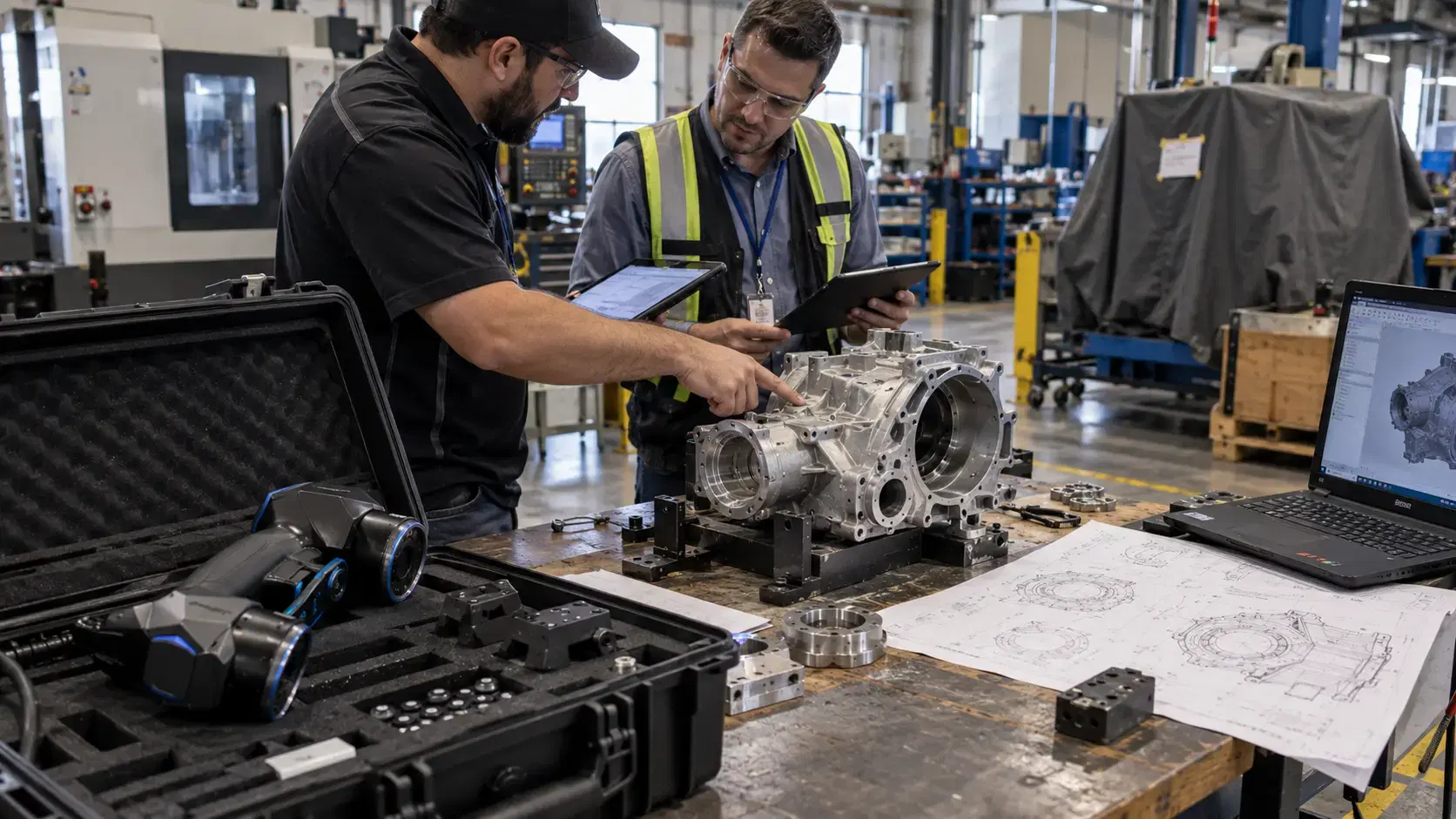
Learn whether 3D scanners are illegal, what legal risks can arise, and how permission, privacy, IP, contracts, and responsible data use affect scanning projects.
Learn how Creaform 3D scanners support quality control, CAD modeling, reverse engineering, inspection, and product design with accurate scan data.

Whether you're evaluating 3D scanners, inspection software, reverse engineering workflows, or CAD modeling services, our engineering team can help identify the best solution for your application.


