This guide explains the scan to CAD workflow, from 3D scanning and mesh cleanup to alignment, feature extraction, CAD reconstruction, software selection, and final engineering output.
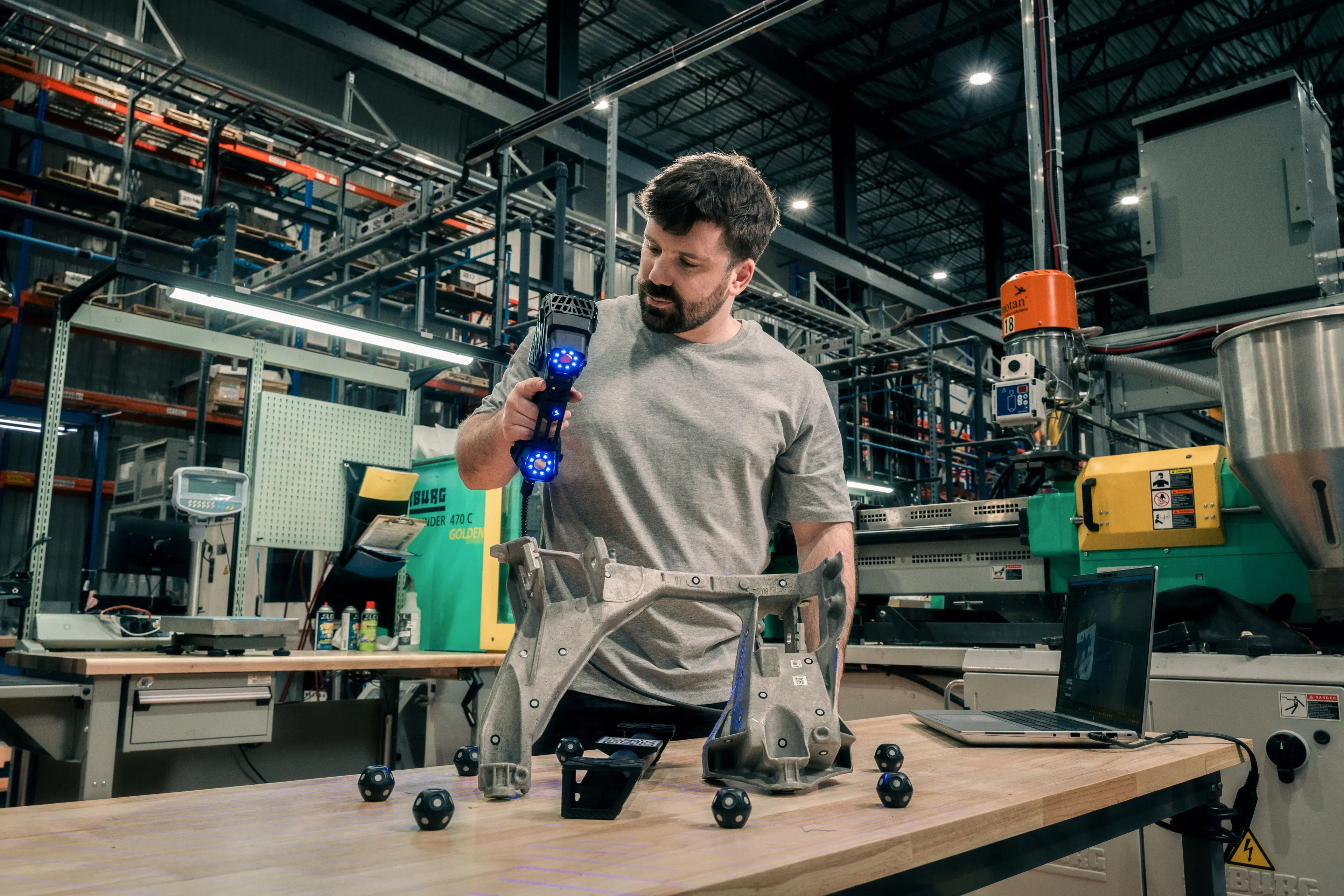
A physical part does not become an engineering file just because someone scans it.
That is where many reverse engineering projects go sideways. The scan captures the shape, but the scan to CAD workflow turns that shape into something engineering, machining, inspection, or product development teams can actually use.
A mesh file may help you 3D print a copy. A proper CAD file helps you revise the design, quote the part, machine it, inspect it, or build an assembly around it.
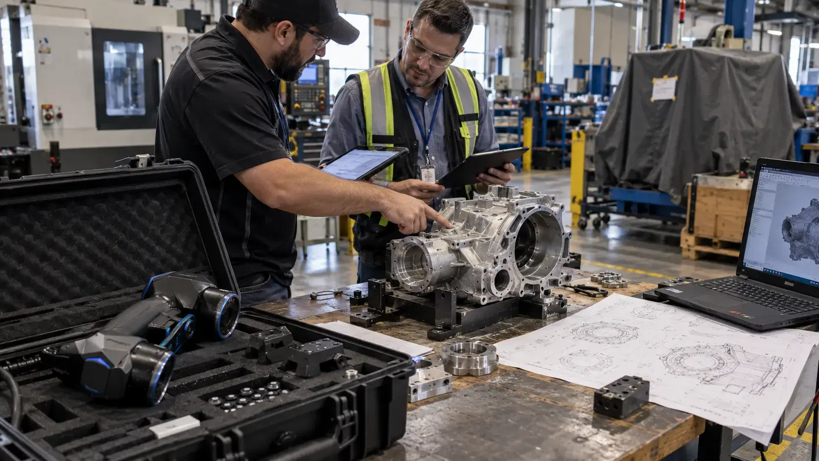
Picture a maintenance manager standing over a worn aluminum housing from a 20-year-old production machine.
The OEM no longer stocks the part. The drawing in the archive shows three views, but no 3D model. The casting has blended surfaces, bolt bosses, draft angles, and one repaired section near a flange.
A machinist can measure the bolt pattern. A caliper can catch the obvious dimensions. But nobody wants to rebuild the whole part from a dozen hand measurements and a guess.
This is exactly where scan-to-CAD work belongs.
A 3D scanner captures the existing geometry. Software cleans the mesh, aligns it to a coordinate system, extracts features, and helps the engineer rebuild a usable model. The final file may become a STEP model, an editable SOLIDWORKS file, an inspection reference, or a corrected design for a new manufacturing process.
The key point is simple: scanning is data capture. CAD reconstruction is engineering judgment.
A scan to CAD workflow usually follows a practical sequence. The exact tools change, but the logic stays the same.
The team scans the physical part with a handheld or metrology-grade 3D scanner. The scanner collects millions of points across the surface and builds a polygon mesh.
The better the scan, the cleaner the downstream CAD work. Missed surfaces, poor alignment, shiny material, or unstable fixturing can create hours of cleanup later.
The raw mesh needs preparation. In Creaform.OS Scan-to-CAD, this can include cleaning mesh data, filling holes, merging meshes, decimating heavy data, and making the mesh watertight.
That does not mean the operator should erase every imperfection. Wear, weld distortion, and casting shift may tell the engineer what happened to the part. The cleanup step should remove scan noise, not useful evidence.
The scan needs a coordinate system before it can support CAD modeling or inspection. Alignment may use datums, planes, cylinders, best-fit methods, or feature-based references.
This step matters more than many new users realize. A 0.2 mm modeling error may not come from the scanner. It may come from a poor alignment strategy.
The software helps pull useful geometry from the mesh. That can include planes, cylinders, curves, cross-sections, NURBS surfaces, 2D sketches, and 3D entities.
For a machined bracket, the engineer may extract flat faces, hole centers, and mounting datums. For a molded housing, they may use section curves and surface patches to rebuild freeform areas.
This is where the scan becomes CAD. The engineer creates clean features such as extrudes, revolves, cuts, fillets, holes, and surfaces.
The goal is not always to copy the part exactly. If the part is worn, damaged, or hand-modified, the CAD model may need to reflect the original design intent rather than the as-found condition.
The final data may move into SOLIDWORKS, Autodesk Inventor, Fusion 360, Solid Edge, or another CAD platform. Common file outputs include STEP, IGES, DXF, STL, OBJ, and native CAD data depending on the software.
That final handoff determines whether the project was useful. A pretty mesh that nobody can edit is not the same as an engineering file.
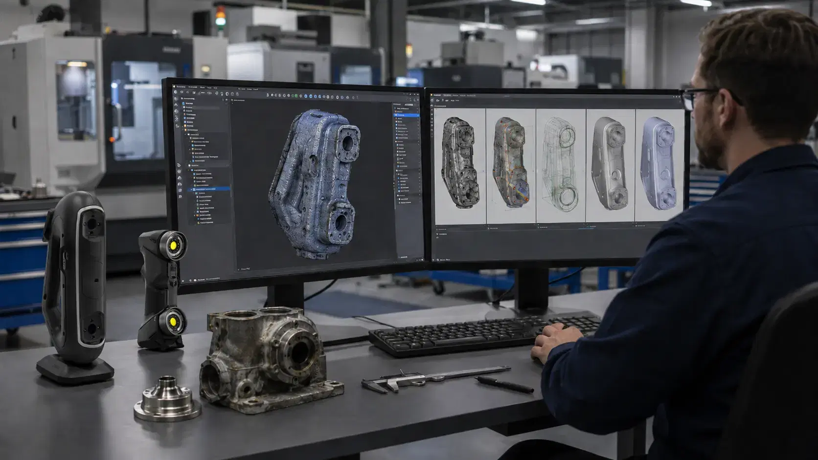
The right scan to CAD software for SOLIDWORKS depends on how much CAD reconstruction your team plans to do.
Creaform.OS Scan-to-CAD module works well for teams already using Creaform scanners and needing a direct route from mesh cleanup to CAD preparation. It supports mesh editing, entity extraction, sketch creation, surface work, and transfer into major CAD platforms.
Peel.CAD Pro fits users working with Peel 3 scanners who need a stronger reverse engineering environment than a simple scan bridge. It includes advanced alignment, entity extraction, sketching, modeling tools, and timeline transfer into SOLIDWORKS.
Geomagic Design X is built for heavier reverse engineering work. It combines scan processing with history-based CAD so users can create editable solid models from scan data. It makes sense when the shop needs parametric output and works with scan data often.
PolyWorks|Modeler is strong when teams need to extract CAD entities from polygonal models. It can create curves, surfaces, parametric sketches, and prismatic features that become the starting point for professional CAD modeling.
DezignWorks is a practical fit for SOLIDWORKS and Autodesk Inventor users who want to create parametric features directly inside their CAD environment. Dynamic 3D lists DezignWorks compatibility with Creaform, Peel 3, FARO, Romer, and other 3D measurement tools.
Scan-to-CAD work pays off when physical parts carry information that drawings do not.
A maintenance team may need to reproduce a discontinued guard, bracket, pump component, or machine cover. Instead of hand-building the model from scratch, the scan gives the CAD operator a measured reference.
A product development team may scan a clay model, foam prototype, or hand-shaped ergonomic grip. The designer can then rebuild the surface cleanly and bring it into CAD for refinement.
A tooling team may scan a die, fixture, or mold insert before repair. The scan captures the current geometry, while the CAD model helps document the intended correction.
A supplier quality team may scan a delivered part and compare it to nominal CAD. If the part does not match the model, the same data can support both inspection and reverse engineering changes.
The best candidates usually have one of three problems: missing CAD, complex geometry, or a physical part that has changed over time.
The first mistake is expecting one-click CAD. Software has improved, but scan-to-CAD still needs engineering judgment. A clean mesh does not know whether a worn hole should stay at 10.18 mm or return to a nominal 10.00 mm.
The second mistake is scanning without a deliverable. Before scanning, decide whether the project needs a mesh, surface model, parametric solid, inspection comparison, or 2D drawing. Each output changes the amount of work required.
The third mistake is ignoring part condition. A bent bracket, repaired housing, or worn casting may not represent the original design. The CAD operator needs to know whether to model the real object or the intended part.
The fourth mistake is choosing software only by brand. The better question is how the team works. A SOLIDWORKS-heavy shop may care more about parametric transfer. A metrology team may care more about alignment, inspection, and traceability. A design group may care more about surface rebuilding and fast edits.
A 3D scan is measured surface data, usually stored as a mesh. A CAD model is an engineering model made from editable features, surfaces, sketches, and dimensions. Scan-to-CAD software helps convert the scan into CAD geometry, but an engineer still has to decide how the final model should behave.
Yes, many scan-to-CAD tools support SOLIDWORKS workflows. Some transfer entities or modeling history into SOLIDWORKS, while others export standard files such as STEP, IGES, or DXF for use in CAD.
The final accuracy depends on the scanner, part condition, alignment method, operator skill, and modeling approach. A high-quality scan can still produce poor CAD if the engineer models the wrong design intent or aligns the part incorrectly.
Usually, yes, if the goal is reverse engineering. A scanner may create a mesh, but scan-to-CAD software provides the tools to clean the data, extract geometry, build surfaces, and create usable engineering files.
Before a team scans a part, it should ask one question: what do we need this file to do?
If the file only needs to support 3D printing, a watertight mesh may be enough. If it needs to drive machining, supplier quoting, fixture design, or product redesign, the shop needs a real CAD workflow.
That decision changes the scanner, the software, the operator, and the deliverable. It also prevents the most common reverse engineering problem, spending time creating data that nobody can use.
Ready to move from manual inspection to metrology-grade 3D scanning? Talk to our team at Dynamic 3D, we'll match you with the right Creaform system for your application and budget.
Meta description: See how a scan to CAD workflow turns 3D scans into engineering files for reverse engineering, SOLIDWORKS modeling, inspection, and manufacturing.
Expand your knowledge with additional resources designed to help engineers, manufacturers, and quality teams make more informed decisions.
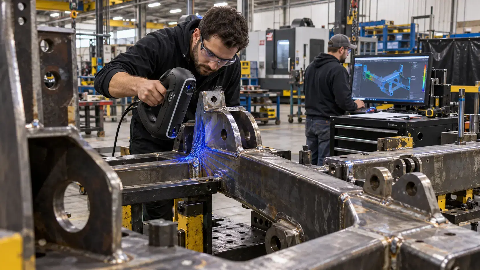

Learn how the HandySCAN 3D BLACK Series supports portable 3D scanning for inspection, reverse engineering, CAD comparison, product design, and quality control.

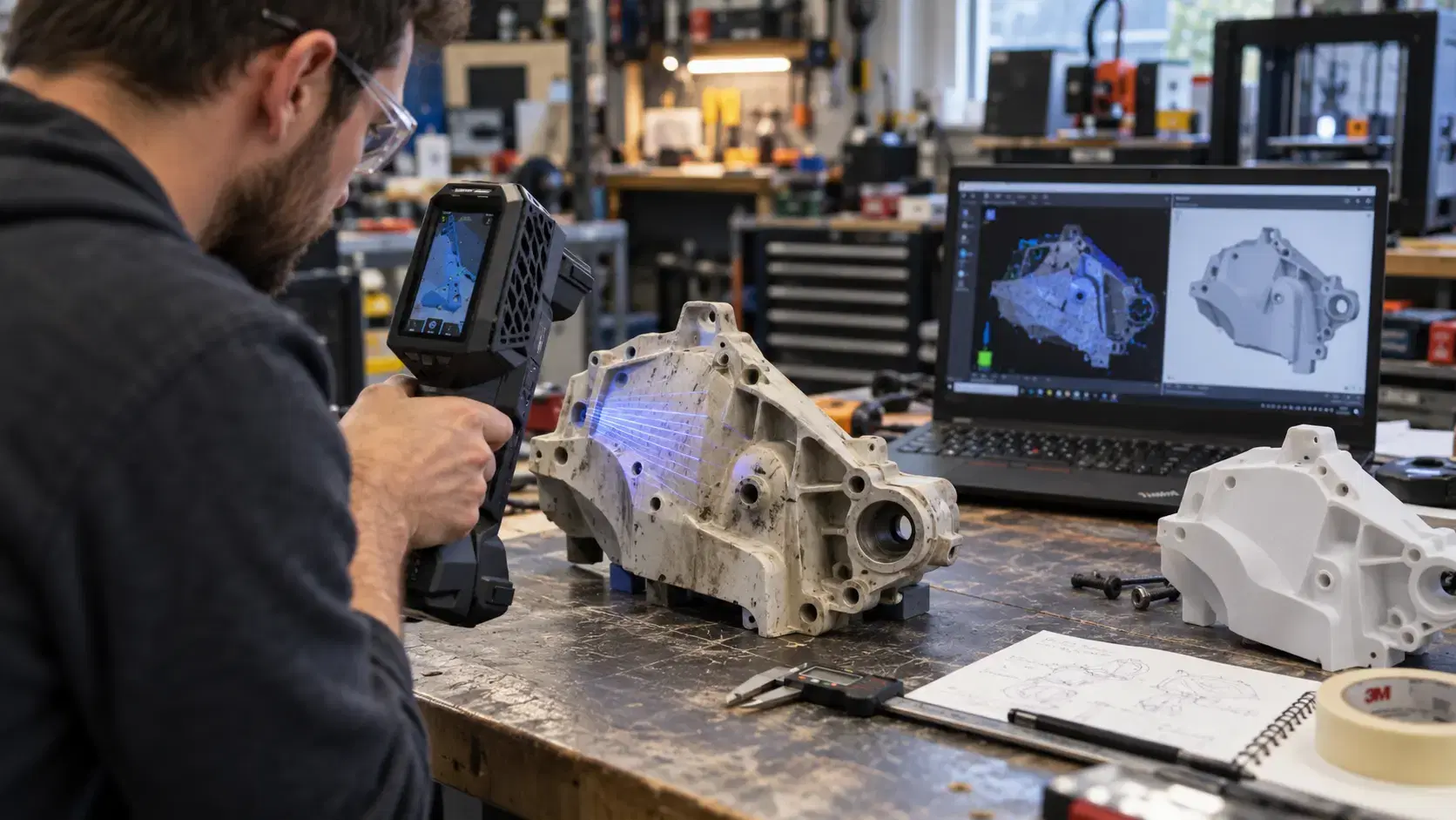
Learn how the Peel 3D scanner supports reverse engineering, product design, 3D printing, inspection, and documentation with practical handheld scanning.
Learn whether 3D scanners are illegal, what legal risks can arise, and how permission, privacy, IP, contracts, and responsible data use affect scanning projects.

Whether you're evaluating 3D scanners, inspection software, reverse engineering workflows, or CAD modeling services, our engineering team can help identify the best solution for your application.


