Learn how parametric modeling with SolidWorks creates editable CAD models, improves design changes, supports manufacturing, and keeps engineering intent clear.
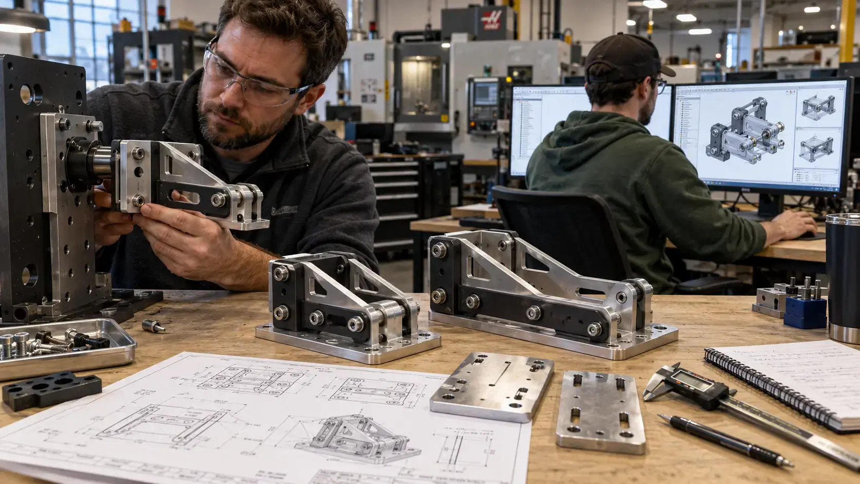
Good product design needs more than a shape that looks correct on the screen.
Engineers also need control. Dimensions may change, features may move, parts may need new holes, and assemblies may need to fit updated requirements. That is why parametric modeling with solidworks is useful for design and manufacturing teams.
Parametric modeling allows a CAD model to be built with dimensions, constraints, relationships, and editable features. Instead of redrawing a part every time something changes, engineers can adjust key values and update the model more efficiently.
If you are asking what is parametric cad, the simple answer is rule-based 3D modeling.
In parametric CAD, geometry is controlled by parameters. These parameters may include dimensions, angles, patterns, equations, feature relationships, sketches, mates, and design intent.
For example, a bracket may have a base length, hole diameter, wall thickness, bend radius, and spacing between mounting holes. If those values are built correctly, the model can update when the dimensions change.
This makes parametric CAD different from simple static modeling. The model is not just a shape. It is a design system that understands how features relate to each other.
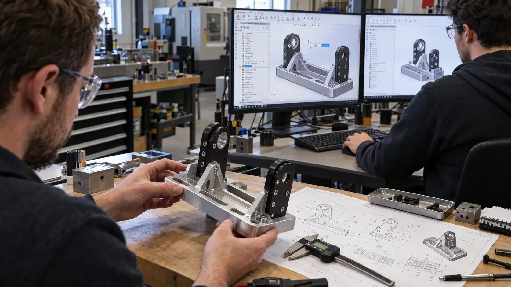
What are parametric cad models? They are editable 3D models built with controlled design logic.
A parametric model may include sketches, extrudes, cuts, fillets, holes, patterns, reference planes, equations, configurations, and assembly relationships. Each feature depends on earlier information in the design tree.
This structure helps engineers make changes without breaking the whole model. If a part needs to become longer, thicker, shorter, or wider, the model can often update through dimension changes instead of complete reconstruction.
Good parametric models also make design intent clearer. Another engineer can open the file and understand why features are placed where they are.
SolidWorks is widely used for mechanical design because it supports feature-based modeling, assemblies, drawings, configurations, and manufacturing workflows.
In SolidWorks, engineers can create sketches, define dimensions, apply constraints, build features, and organize the model in a design tree. This makes it easier to manage design changes, review geometry, and prepare files for manufacturing.
SolidWorks is especially useful for mechanical parts, product assemblies, fixtures, enclosures, brackets, tools, housings, and production components.
When used correctly, it helps teams move from concept to detailed design with better control.
Parametric cad modeling is valuable because engineering work rarely stays fixed.
A customer may request a different size. A supplier may need more clearance. A prototype may reveal that a wall is too thin. A machined part may need a stronger radius. A fastener may change.
With parametric modeling, these updates can be made more cleanly. Instead of rebuilding the entire model, engineers update the relevant dimensions or relationships.
This reduces rework and helps teams test design changes faster.
A parametric model should be built around how the part needs to function.
Mounting holes should relate to datums. Thickness should reflect strength and manufacturability. Features should be controlled by dimensions that matter. Assembly relationships should reflect how parts actually fit together.
This matters because manufacturing depends on clear geometry. A model that looks good but has weak structure can cause problems during drawings, CNC machining, inspection, or future revisions.
Parametric design helps keep the model organized enough for real engineering use.
It also helps suppliers understand design updates, quoted revisions, and inspection expectations before a part moves into final production approval workflows.
Parametric modeling is useful for parts that will change, repeat, or belong to an assembly.
It helps with machined components, sheet metal, molded parts, product housings, fixtures, brackets, tooling, jigs, and configurable designs.
It is also useful when a company needs product families. One base model can support multiple sizes or variations through configurations.
This saves time when designs share common geometry but need different dimensions or features.
The first mistake is building a model without design intent.
If features are placed randomly, the model may fail when dimensions change.
The second mistake is overcomplicating the file. Too many unnecessary references, equations, or dependencies can make edits harder.
The third mistake is ignoring manufacturing needs. A model should consider machining, printing, molding, fabrication, inspection, and assembly.
The fourth mistake is using unclear names. Organized sketches, features, and configurations make the file easier to understand later.
No. Even simple parts benefit when dimensions, holes, and features may change later.
Yes. They can support drawings, CNC files, inspection references, assembly checks, and production planning.
It depends on the task. Parametric CAD is stronger when design intent and future edits matter.
Yes. Reverse engineering and scan-to-CAD workflows can help recreate parts as editable parametric models.
Parametric modeling with solidworks helps teams create CAD files that are easier to edit, review, and manufacture.
It gives engineers more control over dimensions, relationships, assemblies, and future design changes.
Dynamic 3D can help teams connect 3D scanning, reverse engineering, scan-to-CAD, and parametric CAD modeling workflows to create smarter engineering files for product design, manufacturing, inspection, and long-term documentation.
Expand your knowledge with additional resources designed to help engineers, manufacturers, and quality teams make more informed decisions.
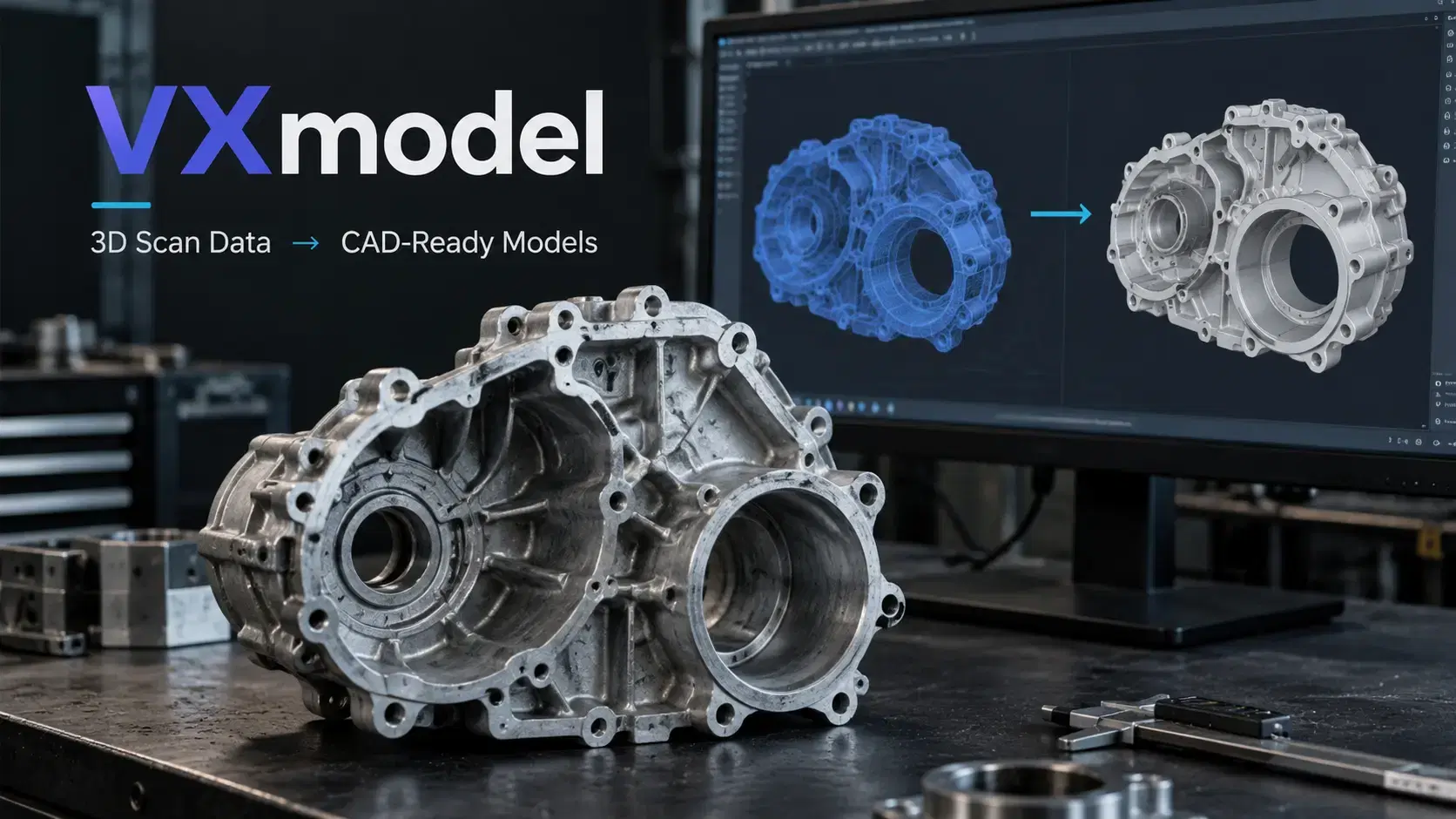

Learn how VXmodel software turns 3D scan data into CAD-ready models using mesh cleanup, alignment, feature extraction, scan-to-CAD workflows, and CAD transfer.

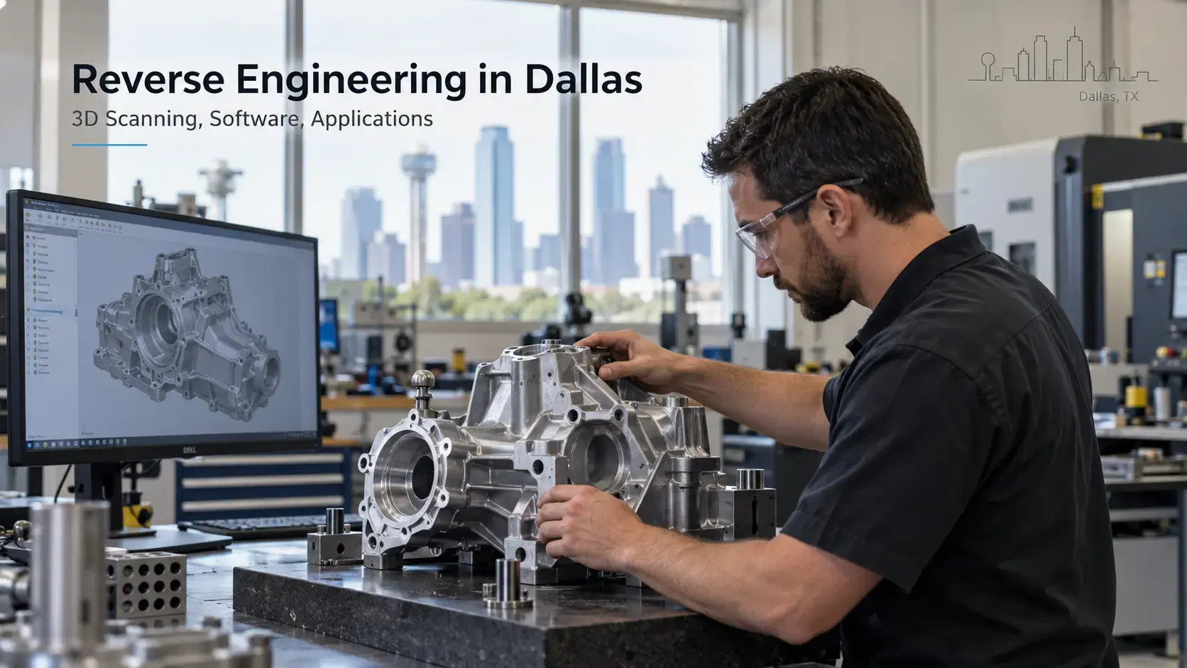
Learn how reverse engineering Dallas services use 3D scanning, reverse engineering software, scan-to-CAD, and inspection to create accurate digital models.
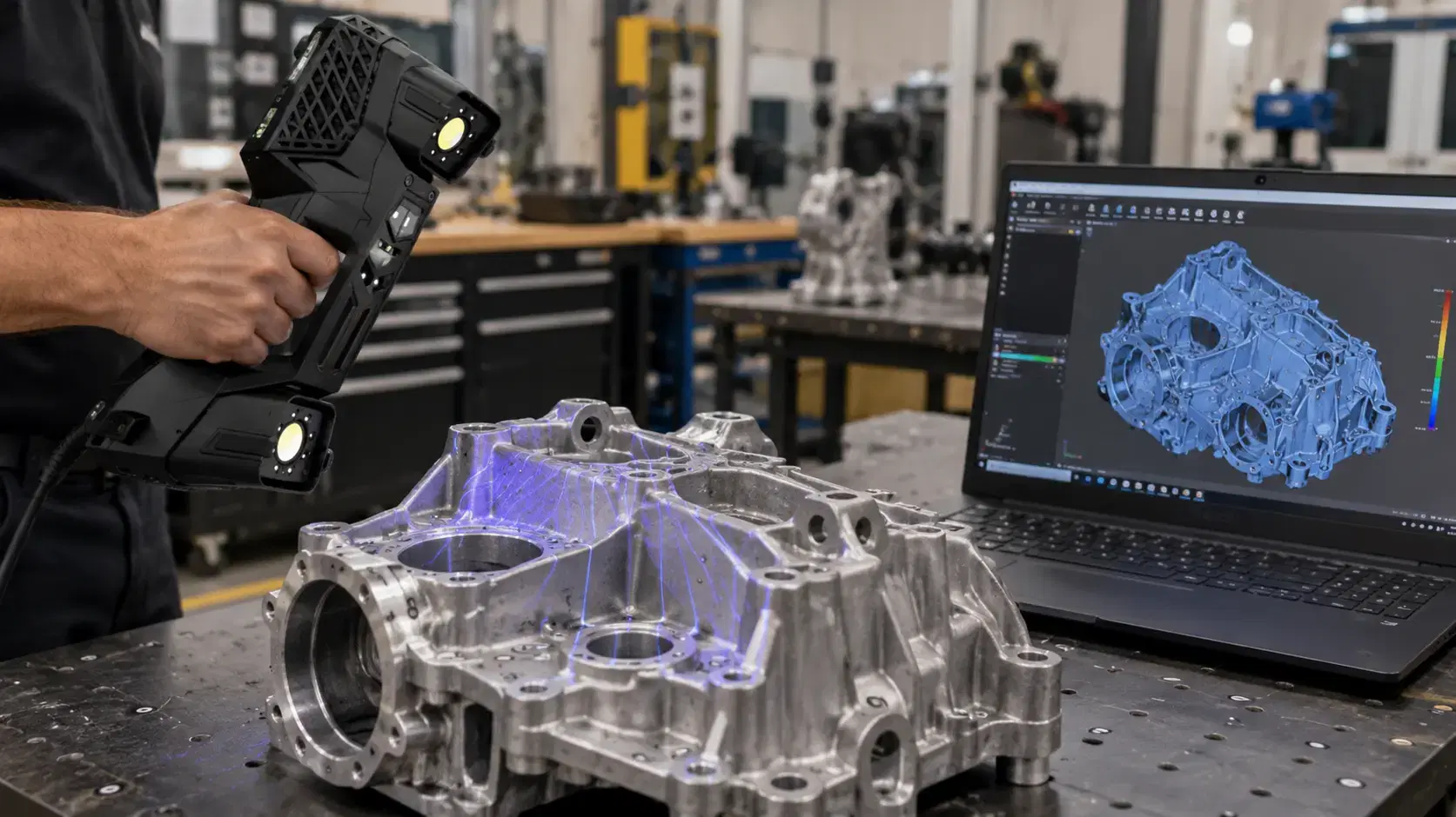
Learn how 3D scanning for reverse engineering turns physical parts into usable digital models through scanning, mesh processing, and scan-to-CAD workflows.

Whether you're evaluating 3D scanners, inspection software, reverse engineering workflows, or CAD modeling services, our engineering team can help identify the best solution for your application.


