Learn what is GD&T in manufacturing, how it controls geometry, tolerances, datums, and part relationships, and why it matters for quality control.
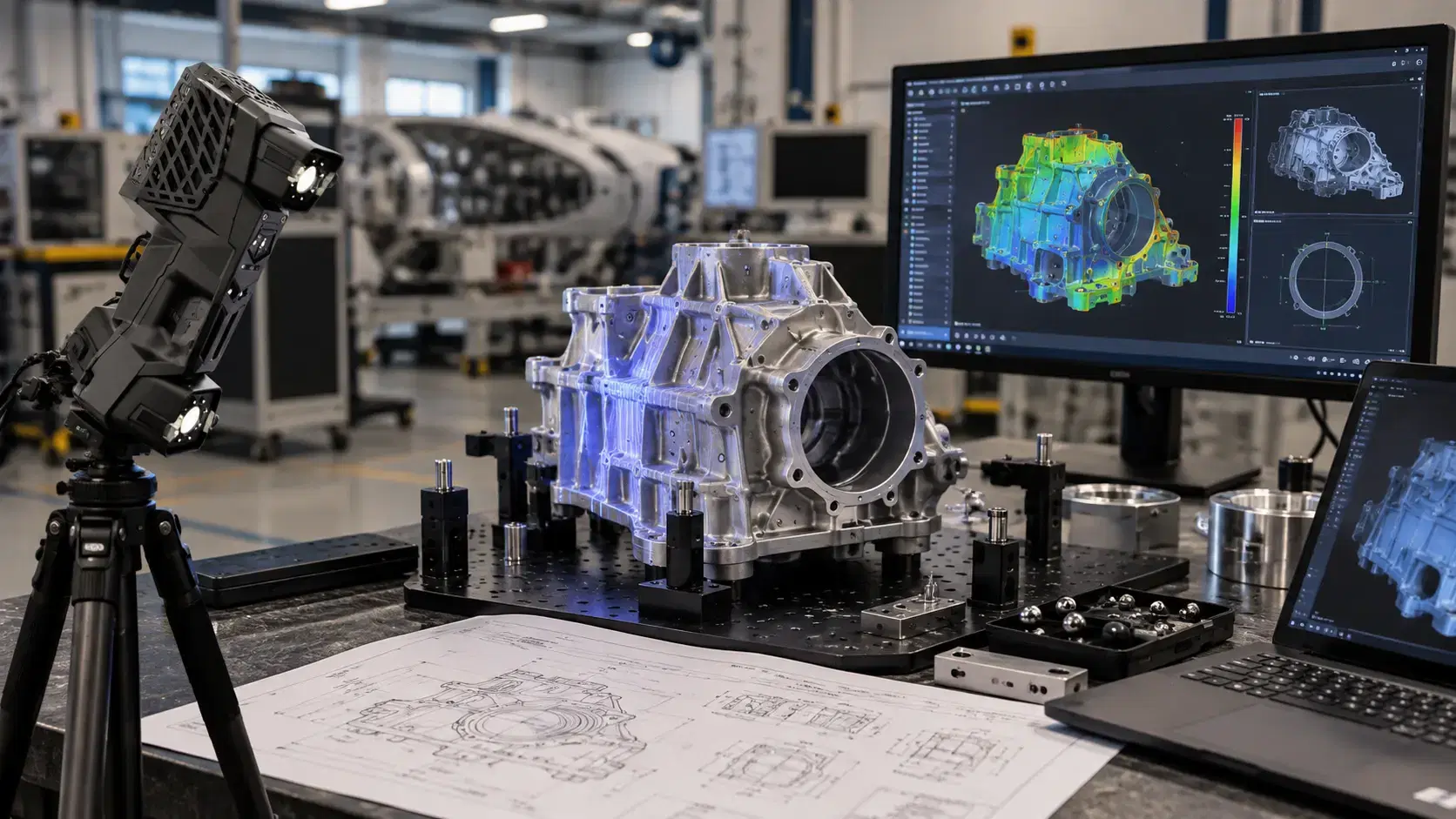
A part can meet a basic size measurement and still fail in assembly.
That is one reason manufacturers use GD&T. If you are asking what is gd&t in manufacturing, it is a system for defining part geometry, allowable variation, and functional requirements on engineering drawings. It helps teams communicate more clearly than simple plus-or-minus dimensions alone.
That shared language helps prevent expensive misunderstandings on the shop floor early.
GD&T stands for geometric dimensioning and tolerancing.
It is a standardized drawing language that describes the allowable variation of a part’s form, orientation, location, and runout. Instead of only saying a hole must be a certain size, GD&T can define where that hole must be in relation to datums, how flat a surface must be, or how much a feature can vary while still working.
This is important because real parts are never perfect. Manufacturing always creates small variations. GD&T explains which variations are acceptable and which ones affect function.
If you are asking what is gd&t in engineering, think of it as a way to protect design intent.
Engineers use GD&T to describe how parts should fit, move, seal, align, or assemble. A bracket may need holes in the correct position. A machined face may need flatness. A shaft may need circularity. A mating component may need perpendicularity to keep assembly square.
Without GD&T, drawings can leave too much room for interpretation. Two suppliers may read the same drawing differently. One inspector may measure from a different reference than another.
GD&T reduces that confusion by defining datums, feature control frames, tolerance zones, and measurement relationships.
Quality control is not only about checking whether a number is close.
It is about confirming whether the part will work. GD&T helps inspectors measure the features that affect fit, function, safety, and performance.
For example, a hole may have the correct diameter, but if its position is wrong, the bolt will not fit. A surface may be the right height, but if it is not flat enough, the assembly may rock or leak. A cylinder may measure the correct size, but if it is out of round, it may not rotate smoothly.
GD&T helps quality teams catch these problems before parts reach assembly or customers.
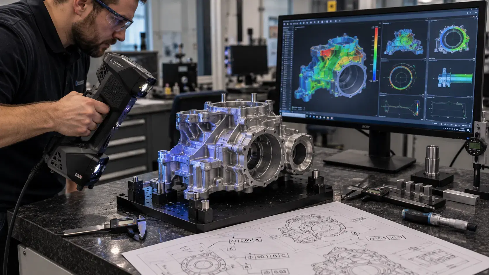
GD&T includes several types of controls.
Form controls include flatness, straightness, circularity, and cylindricity. These describe the shape of an individual feature.
Orientation controls include parallelism, perpendicularity, and angularity. These describe how one feature relates to another.
Location controls include position, concentricity, and symmetry. Position is common for holes, slots, pins, and mounting features.
Profile controls can define complex surfaces, curves, and freeform shapes. Runout controls help manage rotating parts.
Each control answers a different inspection question.
Datums are reference features used to locate and orient the part during measurement.
They act like the starting point for inspection. A drawing may define a primary, secondary, and tertiary datum so the inspector knows how the part should be held and measured.
This matters because a part can measure differently depending on how it is positioned. Datums reduce argument by making the reference structure clear.
For manufacturing teams, good datum selection can make inspection faster, fixturing easier, and results more repeatable.
Traditional inspection tools are useful for many GD&T checks, especially simple dimensions and controlled point measurements.
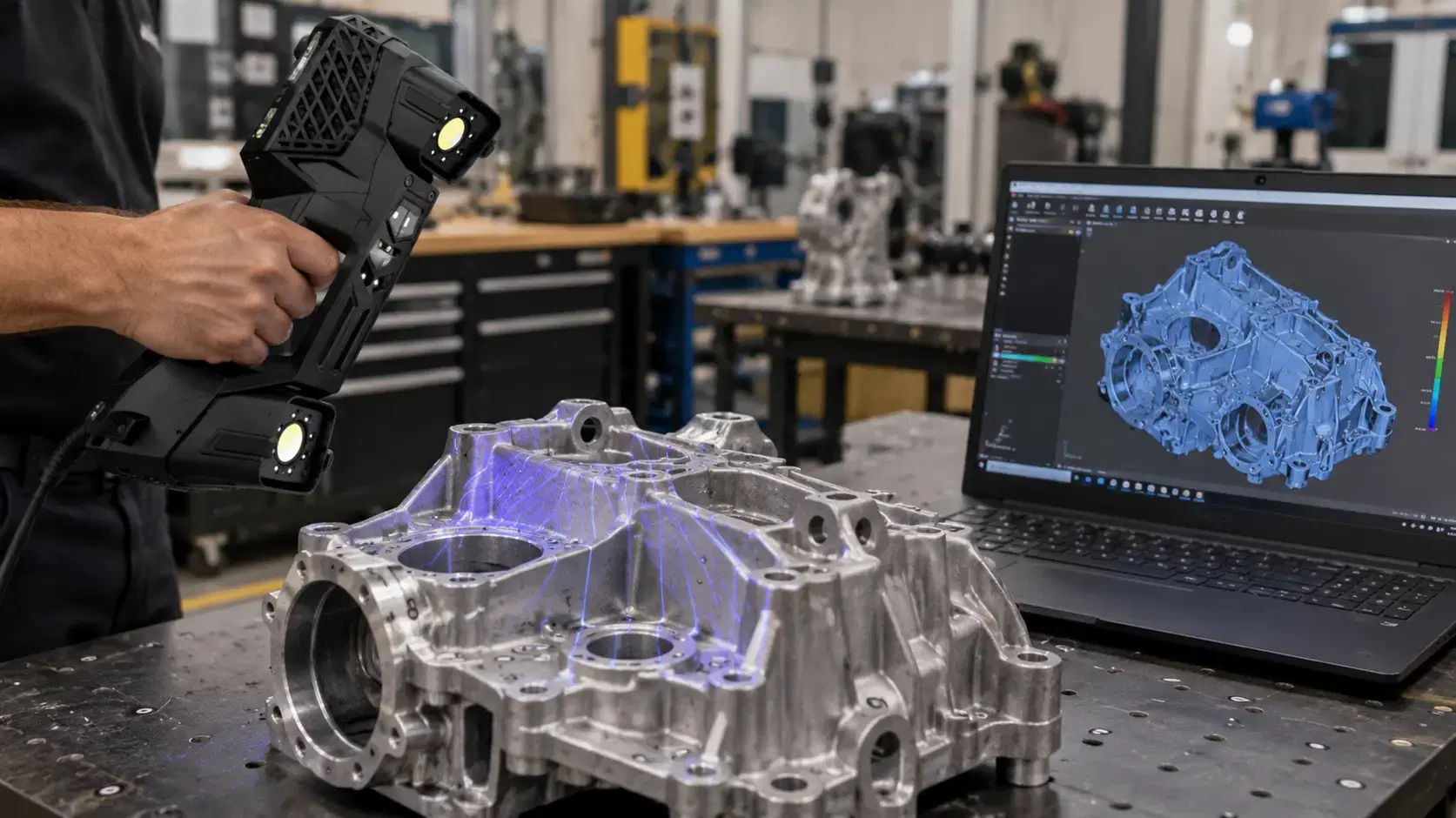
However, complex parts often need more surface data. 3D scanning can capture full geometry and compare the physical part to CAD. Inspection software can then show color maps, profiles, sections, and measured features.
This is helpful for castings, molded parts, sheet metal, weldments, tooling, and freeform surfaces where shape variation is difficult to understand from a few manual checks.
A 3D scan does not replace engineering judgment, but it gives quality teams clearer evidence.
Manufacturers should use GD&T when part function depends on more than simple size.
It is especially useful for assemblies, mating parts, tight interfaces, moving components, sealing surfaces, hole patterns, fixtures, tooling, and high-value production work.
GD&T is also important when multiple suppliers, machines, or inspection teams work on the same part. It creates a shared language that supports consistent manufacturing and quality control.
The earlier GD&T is considered, the better. Adding it after production problems appear can help, but using it during design can prevent those problems.
No. Engineers create it, but machinists, inspectors, quality teams, and suppliers all use it.
Not always. Good GD&T can make requirements clearer and prevent unnecessary tight tolerances.
Yes, especially for profile, surface comparison, and complex geometry when paired with proper software and alignment.
Datums define how the part is referenced during inspection, which makes results more consistent.
GD&T helps manufacturers move beyond vague drawings and unclear inspection methods.
It defines what matters, how features relate, and how variation should be controlled. That makes quality control more practical, repeatable, and connected to real function.
Dynamic 3D can help manufacturers use 3D scanning, dimensional inspection, and scan-to-CAD workflows to support GD&T inspection, part validation, and better manufacturing decisions.
Expand your knowledge with additional resources designed to help engineers, manufacturers, and quality teams make more informed decisions.
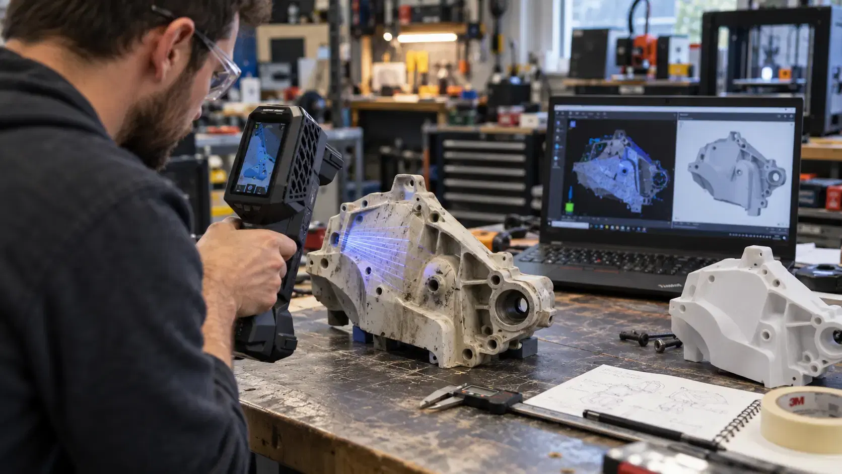

Learn how the Peel 3D scanner supports reverse engineering, product design, 3D printing, inspection, and documentation with practical handheld scanning.

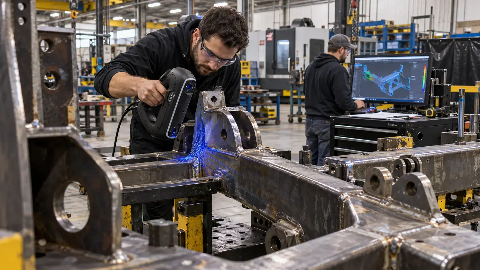
Learn how the HandySCAN 3D BLACK Series supports portable 3D scanning for inspection, reverse engineering, CAD comparison, product design, and quality control.
Learn how 3D scanning for reverse engineering turns physical parts into usable digital models through scanning, mesh processing, and scan-to-CAD workflows.

Whether you're evaluating 3D scanners, inspection software, reverse engineering workflows, or CAD modeling services, our engineering team can help identify the best solution for your application.


